Method of manufacturing a golf club head

a manufacturing method and golf club technology, applied in the field of golf club manufacturing methods, can solve the problems of inconvenient manufacturing, inconvenient manufacturing, and inability to meet the needs of golf clubs, etc., and achieve the effect of reducing the cost of manufacturing, and improving the quality of golf clubs

Inactive Publication Date: 2004-03-30
ENDO MFG COMPANY
View PDF6 Cites 39 Cited by
  • Summary
  • Abstract
  • Description
  • Claims
  • Application Information

AI Technical Summary

Problems solved by technology

Furthermore, as club heads of the same club number sometimes define slightly different configurations per each production lot number, there occurs a problem that the use of a receiving die that does not fit in with the configuration of a certain head could damage products or cause irregular face lines to be formed, so that it has been necessary to modify the receiving die every time the production lot number changes.
Accordingly, the manufacture and modification of linear dies, impressing stamp dies and receiving dies have been too expensive and too time consuming.
As a result, there has been a problem that production process and method are subject to many restrictions.
Besides, as metallic materials having high hardness or low toughness are not suitable for cold press, there has been a problem that it is difficult to form face lines or the like in the case that such materials are used.
According to such conventional marking method, however, the marking on a sole surface or the like is liable to be easily worn away due to the frictional contact with the earth.
Further, whilst a face line needs to be formed as a concavity in order to apply spin to a ball, a face line formed by the above conventional marking method merely varies the color tone of the surface of a club head, and thus such face line is of no use.

Method used


Image

  • Method of manufacturing a golf club head
  • Method of manufacturing a golf club head
  • Method of manufacturing a golf club head

Examples


Embodiment Construction

Hereinafter will be described embodiments of the invention with reference to the attached drawings, in which an iron golf club is described as an example.

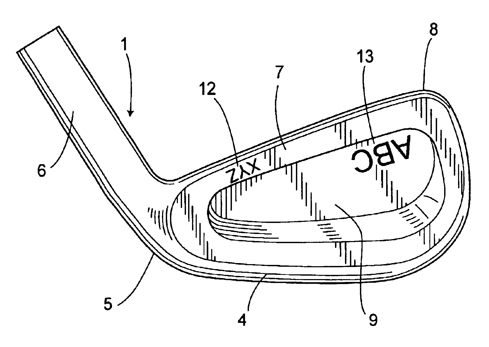
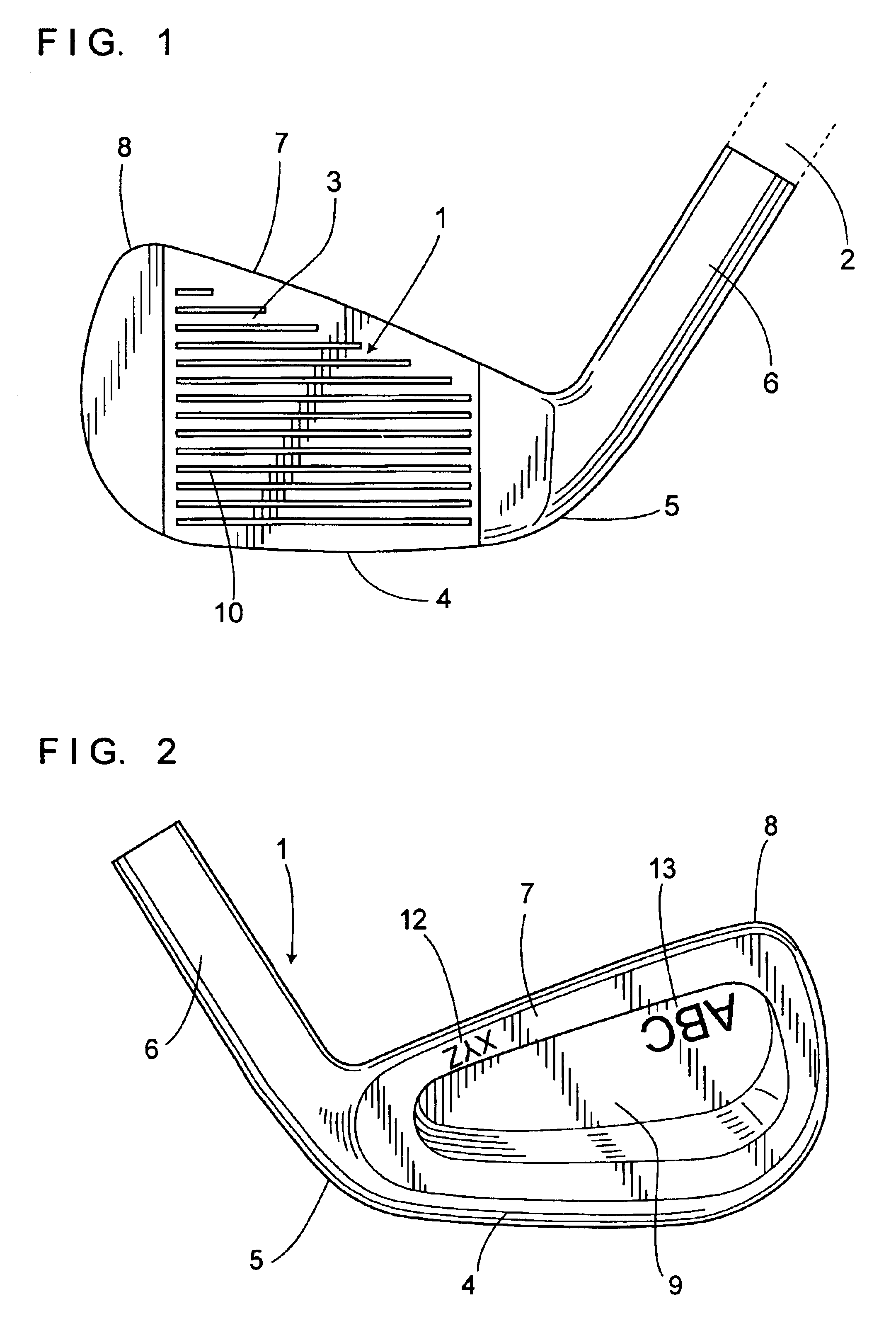
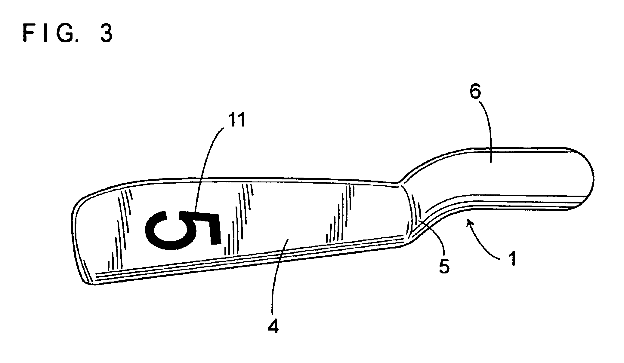
As shown in FIGS. 1 through 3, an iron golf club is made up of a head 1 and a shaft 2, of which the head 1 is made from a metallic material such as low-carbon steel, stainless steel or titanium-based alloy, including a face 3 for striking balls on a front, a sole 4 on a bottom, a heel 5 on one side, a toe 8 on the other side, a shaft attachment portion 6 provided at an upper part of the heal 5 for connecting the shaft 2 thereto and a top 7 at a top portion, respectively. A rear surface of the head 1 is formed with a cavity 9, substantially opposite to the face 3.

The face 3 is formed with a plurality of face lines 10 extending laterally, respectively. Each face line of a V-shaped or a U-shaped profile is formed as a concave portion on a surface of the face 3, using a laser processing machine. The sole 4 is formed with a club number ...


PUM

PropertyMeasurementUnit
loft angleaaaaaaaaaa
lengthaaaaaaaaaa

Abstract

A method of manufacturing a golf club head by which face lines, a club number display and logo marks can be formed without being affected by the configuration and material of the club head. Face lines 10, a club number display 11 and logo marks 12 and 13 are formed on the surface of a golf club head 1, using a laser beam processing machine. Stamps and receiving dies are no longer required for a respective production lot number or a respective club number, so that costs and time required for fabricating impressing stamp dies and receiving dies can be saved. Further, face lines 10, club number display 11 and logo marks 12 and 13 are able to be formed without being affected by the configuration and material of the golf club head 1.

Description

a) Field of the InventionThe present invention relates to a method of manufacturing a golf club head, having a face line, a club number display and a logo mark on a surface thereof.b) Prior ArtA golf club is made up of a head and a shaft, and it is typically classified into three groups, i.e., a wood, an iron and a putter. The iron and wood are classified according to the loft angle. For the iron, for example, a small loft angle (for example 20.degree. to 30.degree.) iron is referred to as a long iron, while a large loft angle (for example 40.degree. to 50.degree.) iron is referred to as a short iron. Normally, irons are numbered from the long iron to the short iron, for example from No.1 to No.9, and then there is a PW (pitching wedge), a SW (sand wedge), and etc. These numbers and symbols are generally called club numbers, attached to respective club heads.Iron club heads are formed from iron or other various kinds of metallic materials. Whilst wood club heads were formed from woo...

Claims


Application Information

Patent Timeline
Patent Type & Authority Patents(United States)
IPC IPC(8): A63B53/04B23K26/36B23K26/00A63B102/32
CPCA63B53/04B23K26/365A63B53/047B23K2203/04B23K2203/14B23K2201/007B23K26/361B23K2101/007B23K2103/04B23K2103/05B23K2103/14A63B60/00
Inventor TAKEDA, HITOSHI
Owner ENDO MFG COMPANY
Why Eureka
Try Eureka