Method and system for inter-frequency handoff and capacity enhancement in a wireless telecommunications network

a wireless telecommunications network and inter-frequency handoff technology, applied in the field of wireless telecommunications systems, can solve the problems of pilot beacons being expensive, unable to achieve the desired solution, and unable to meet the needs of users,

Inactive Publication Date: 2004-03-30
SPRING SPECTRUM LP
View PDF16 Cites 120 Cited by
  • Summary
  • Abstract
  • Description
  • Claims
  • Application Information

AI Technical Summary

Problems solved by technology

Unfortunately, however, such pilot beacons are expensive.
Therefore, this solution is not desirable.
A problem of a different type can also arise even when a mobile station moves between physical sectors that share the carrier frequency being used by the mobile station.
Consequently, as the mobile station enters the second physical sector and continues to communicate on carrier frequency A, the quality of communications on that carrier in the second physical sector could be quite poor, and the added traffic could result in dropped calls as well.
Unfortunately, however, that increase in power could effectively raise the noise level in the first cell site (as higher power signals are transmitted within the cell) and could consequently reduce capacity in the first cell site.

Method used


Image

  • Method and system for inter-frequency handoff and capacity enhancement in a wireless telecommunications network
  • Method and system for inter-frequency handoff and capacity enhancement in a wireless telecommunications network
  • Method and system for inter-frequency handoff and capacity enhancement in a wireless telecommunications network

Examples


Embodiment Construction

1. Network Architecture

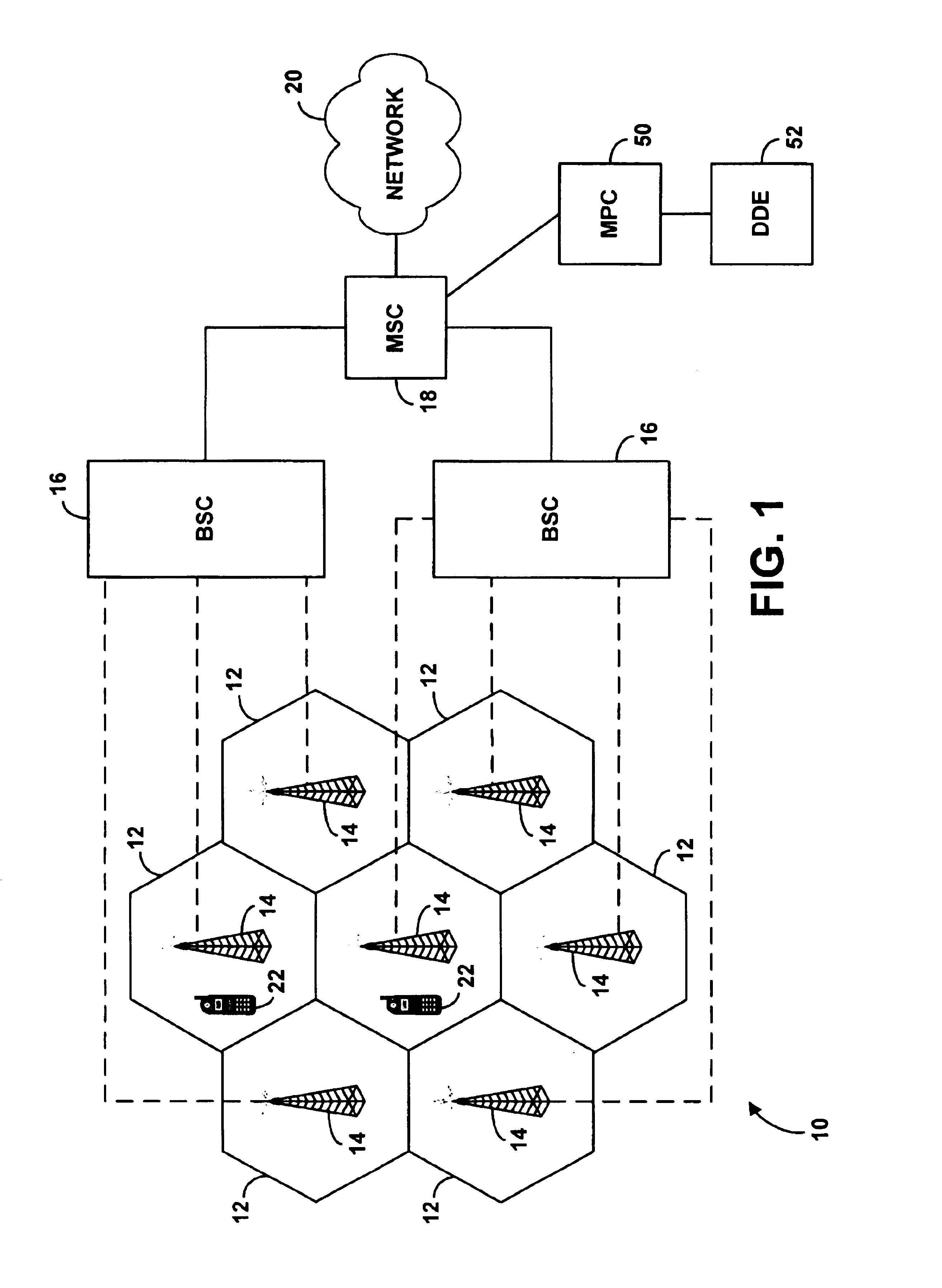
Referring to the drawings, FIG. 1 illustrates a simplified block diagram of a wireless telecommunications network 10 in which an exemplary embodiment of the present invention can be employed. As shown in FIG. 1, network 10 includes multiple cells or cell sites 12, each of which is defined by an RF radiation pattern from a respective BTS 14. FIG. 1 depicts each of the cells in an idealized fashion, as a hexagon that does not overlap other cells. In reality, however, most cells will overlap with neighboring cells and, due to topography, signal strength and other factors, may vary widely in shape and size.

In network 10, the BTS 14 of each cell site communicates with a BSC 16, which in turn communicates with an MSC or gateway 18. The MSC then communicates with a network, such as the PSTN or the Internet for instance. (Other intermediate elements may be provided as well.) In a typical arrangement, the BTS of a cell site manages the air interface between the BTS and...


PUM


Abstract

A method and system for allocating air interface resources in a wireless telecommunications network. A control entity determines the current or projected location of a mobile station. Using the location, the control entity identifies the physical sectors and respective carrier frequencies available to serve the mobile station. The control entity then selects an optimal physical sector and respective carrier frequency and instructs the mobile station to operate in the selected physical sector using the selected carrier frequency.

Description

1. Field of the InventionThe present invention relates to wireless telecommunications systems and more particularly to the allocation of air interface resources in such a system.2. Description of Related ArtIn a typical cellular radio communications system (wireless telecommunications network), an area is divided geographically into a number of cell sites, each defined by a radio frequency (RF) radiation pattern from a respective base transceiver station (BTS) antenna. The base station antennae in the cells are in turn coupled to a base station controller (BSC), which is then coupled to a telecommunications switch or gateway, such as a mobile switching center (MSC) for instance. The MSC may then be coupled to a telecommunications network such as the PSTN (public switched telephone network) or the Internet.When a mobile station (MS) (such as a cellular telephone, pager, or appropriately equipped portable computer, for instance) is positioned in a cell, the MS communicates via an RF a...

Claims


Application Information

Patent Timeline
Patent Type & Authority Patents(United States)
IPC IPC(8): H04Q7/20H04Q7/22H04W36/08H04W36/32
CPCH04W36/32H04W36/08
Inventor OH, DAE-SIKWHITE, BRIAN
Owner SPRING SPECTRUM LP
Why Eureka
Try Eureka