
Systems and methods for trail edge paper suppression for high-speed finishing applications

a technology of high-speed finishing and suppression systems, applied in the field of control sheets, can solve the problems of uneven stacking, large volume and surface area in an office space, and configurations that require considerable volume for the mechanism to controllably move paper sheets

Inactive Publication Date: 2004-04-20
XEROX CORP
View PDF18 Cites 89 Cited by
  • Summary
  • Abstract
  • Description
  • Claims
  • Application Information

AI Technical Summary

Benefits of technology

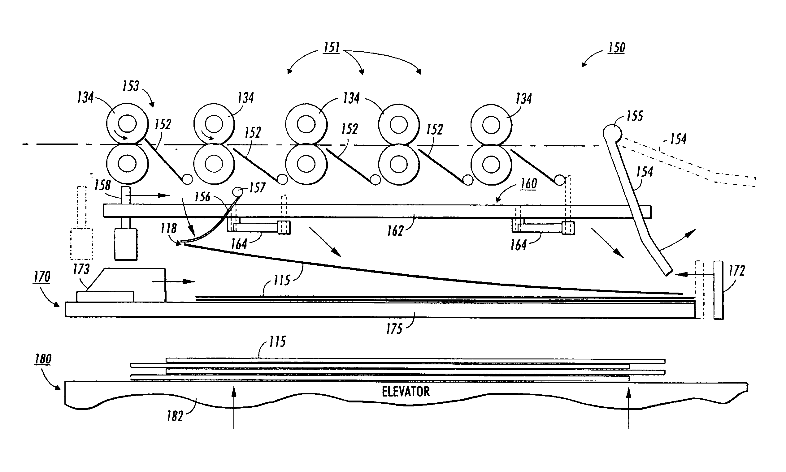
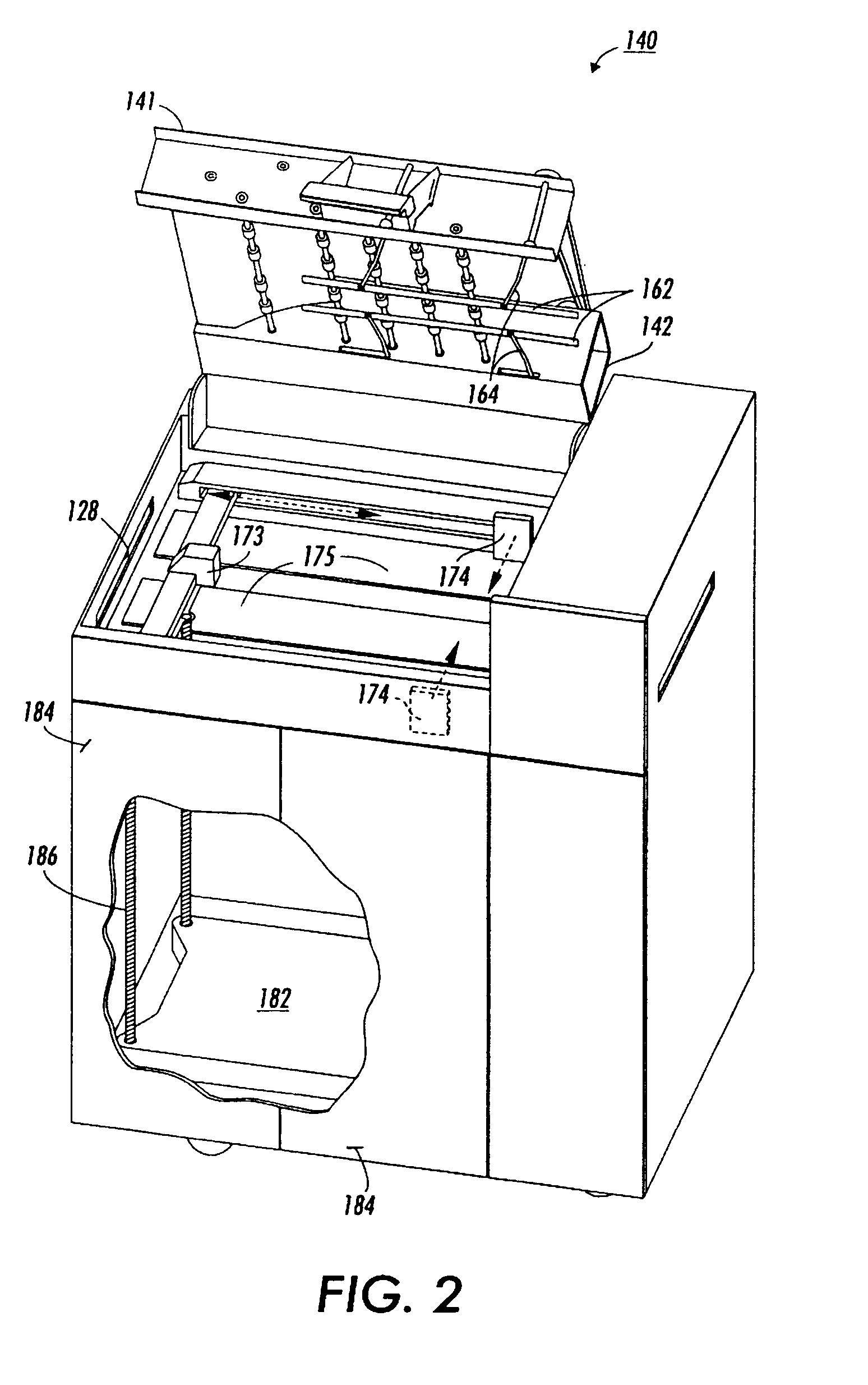
In various exemplary embodiments, the sheet passes through a retracting temporary compiler structure and continues its descent. At the same time, rear paper suppressor structures provided on a diverter assembly swing down and forward to push the trailing edge of the sheet forward, preventing rearward motion of the sheet. Front paper suppressor slats or baffles provided on a front dampener swing down and backwards to intercept the leading edge of the sheet. These baffles operate to prevent the sheet from moving past the front register gate and to pitch the leading edge of the sheet downward. This enables the sheet to stack evenly on the collection tray after passing under the retracting temporary compiler.

Problems solved by technology

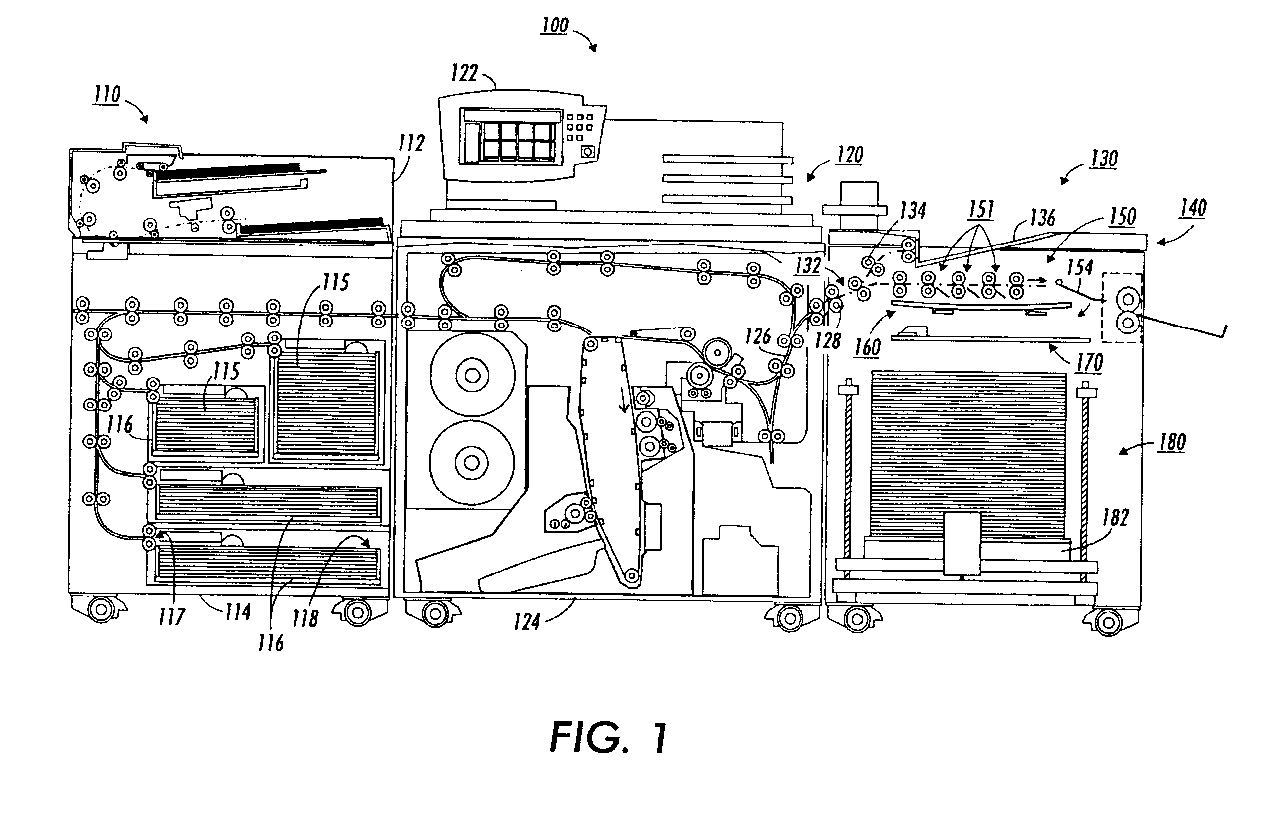
Commercially-available designs for finishing devices are currently either too slow for efficient use in high-speed photocopiers, or present an excessive footprint and thereby consume greater volume and surface area in an office space than is desirable.
Such configurations require considerable volume for the mechanisms to controllably move the paper sheets.
Finishing devices having vertical configurations present either uneven stacking from flutter as the sheets drop or require volume-intensive mechanisms to control the descent of the sheets.

Method used


Image

  • Systems and methods for trail edge paper suppression for high-speed finishing applications
  • Systems and methods for trail edge paper suppression for high-speed finishing applications
  • Systems and methods for trail edge paper suppression for high-speed finishing applications

Examples


Embodiment Construction

A high-speed finishing device confined to a small footprint requires that the settling time of the trailing edge of incoming sheets be controlled. In particular, such control requires paper sheets to exhibit specific and repeatable aerodynamic behavior. In various exemplary embodiments of the finishing device in which the systems and methods according to this invention are usable, a sheet of paper is fed horizontally into the finishing device and passes between pairs of rollers, called nips, to control the velocity of the sheet through the finishing device.

The sheet passes through one of a series of diverter gates. The diverter gate through which a given sheet passes is selected based on the length of the sheet. The diverter gates are arranged in sequence with the first diverter gate for the longest sheets, and progressing downstream towards the last diverter gate for the shortest sheets. The sheet is ejected through the selected diverter gate, and the sheet travels forward while dr...


PUM


Abstract

A paper sheet finishing system includes a sheet guiding mechanism having nip rollers to transport a sheet forward, at least one diverter gate through which the sheet passes when the at least one diverter gate is open, and a temporary compiler to support the sheet after the sheet passes the at least one diverter gate, a diverter member to travel in conjunction with the at least one diverter gate, and at least one rear suppressor member connected to the diverter member to push a trailing edge of the sheet forward and pitch a leading edge of the sheet downward after the sheet controllably descends past the temporary compiler with reduced flutter and improved positioning during compilation of the sheets.

Description

1. Field of InventionThis invention relates to controlling sheet placement in finishing devices.2. Description of Related ArtDevices that process sheets of paper, such as high-speed printers, digital copiers and photocopiers, often require finishing operations to be performed. Such a finishing device causes the paper sheets to be deposited in manner either selected by the user or in a default fashion.Many finishing devices and sheet stacking devices are known in the sheet handling equipment industry, and involve collating or stacking sheets into sets of sheets and finishing each set of sheets by stapling or binding prior to depositing the finished sets of sheets onto a collection tray. Commercially-available designs for finishing devices are currently either too slow for efficient use in high-speed photocopiers, or present an excessive footprint and thereby consume greater volume and surface area in an office space than is desirable.Conventional finishing devices convey paper sheets...

Claims


Application Information

Patent Timeline
IPC IPC(8): B65H29/34B65H31/34B65H29/26
CPCB65H29/34B65H31/3018B65H31/34B65H2301/42194B65H2301/422615B65H2801/27
Inventor ABBATA, SALVATORE A.MILILLO, RICHARD J.FLINT, TERRANCE W.
Owner XEROX CORP
Learn More