

Vehicle air conditioner and mounting structure
- Summary
- Abstract
- Description
- Claims
- Application Information
AI Technical Summary
Benefits of technology
Problems solved by technology
Method used
Image

Examples
first embodiment
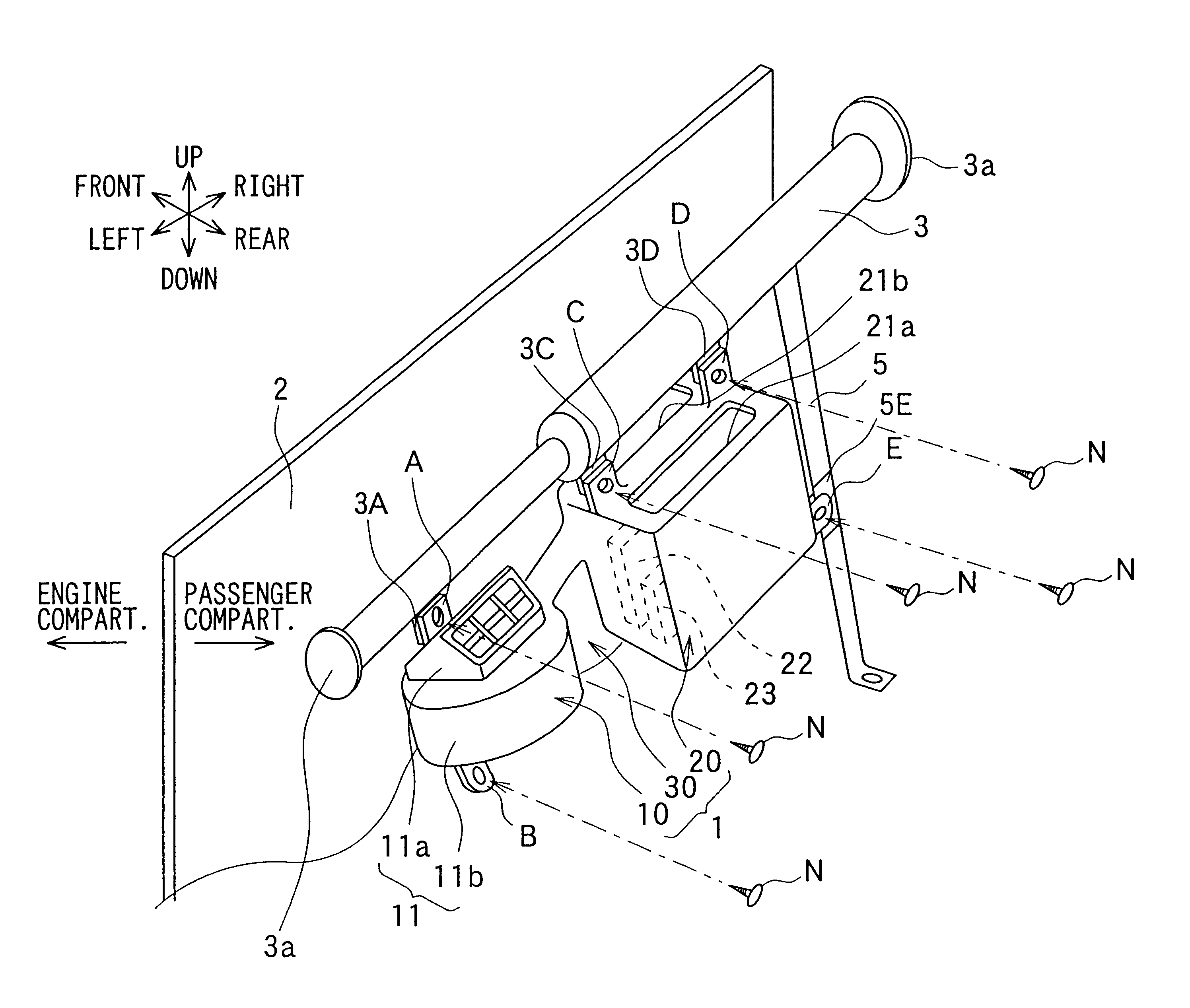
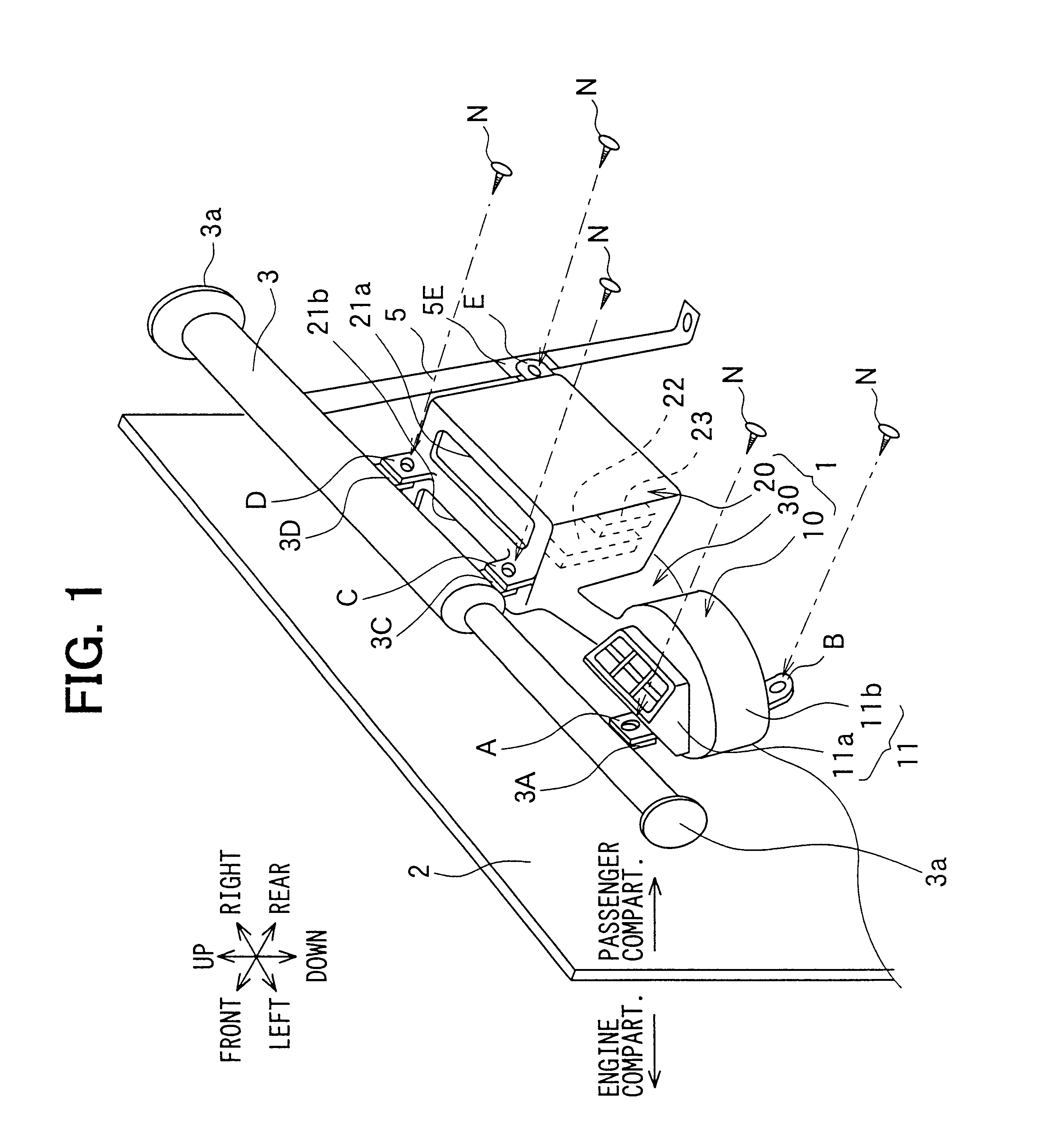
A first preferred embodiment of the present invention will be now described with reference to FIGS. 1-5B. In the first embodiment, an air conditioner 1 is mounted on a vehicle as shown in FIG. 1 to correspond to arrangement directions in a vehicle front-rear direction, a vehicle right-left direction and a vehicle up-down direction, respectively. The air conditioner 1 is supported by and fixed to a strengthening member (supporting member) 3. The strengthening member 3 is located at a side of a vehicle passenger compartment with respect to a partition wall (fire wall) 2 disposed between an engine compartment and the passenger compartment, and is located inside a vehicle dashboard (not shown). The strengthening member 3 extends in the vehicle right-left direction, and is for reinforcing a vehicle body.
Before the strengthening member 3 is attached to the vehicle, various apparatuses such as audio apparatuses other than the air conditioner 1 are integrally attached to the strengthening m...
third embodiment
In the third embodiment, further, the vehicle-side fixing portions 3d of the side bracket 3a are located in a vibration transmittance route from the fixing portion 3c of the blower casing 11b to the steering wheel unit 4 through the side bracket 3a and the strengthening member 3. Therefore, the vibration transmitted from the blower casing 11b to the strengthening member 3 through the side bracket 3a can be effectively reduced in the vehicle-side fixing portions 3d.
Generally, a cowl (not shown), extending in the vehicle right-left direction, is disposed on the vehicle rear side of the partition wall 110, and the cowl has an opening communicating with the outside. The outside air suction port 11g of the inside / outside air switching box 11a is press-fitted into the opening of the cowl through a packing member (urethane foam). Accordingly, when the inside / outside air switching box 11a vibrates greatly, it is difficult to ensure the air-sealing performance of the packing member. In the t...
PUM
 Abstract
Description
Claims
Application Information