Lithographic projection apparatus, device manufacturing method, device manufactured thereby, cleaning unit and method of cleaning contaminated objects

a technology of lithographic projection and projection device, which is applied in the direction of printers, instruments, geological measurements, etc., can solve the problems of radiation beam loss, inability to meet the requirement, and inability to transmit radiation beams

Inactive Publication Date: 2004-04-20
ASML NETHERLANDS BV
View PDF9 Cites 61 Cited by
  • Summary
  • Abstract
  • Description
  • Claims
  • Application Information

AI Technical Summary

Benefits of technology

It is therefore one aspect of embodiments of the present invention to provide a lithographic projection apparatus in which optical components can be cleaned with stable cleaning materials.

Problems solved by technology

These contaminants tend to adsorb to optical components in the system, and cause a loss in transmission of the radiation beam.
Such a loss in transmission is unacceptably high.
Localised contamination on optical components can cause this requirement not to be met.
However, ozone is a very unstable material and degrades only a few hours after its formation.
However, the extra step of producing the ozone itself is highly inconvenient.
As these materials themselves are not effective as cleaning agents, they are used in combination with UV radiation.
Moreover, the risk of re-contamination is much higher for an external cleaning unit due to the longer period of time between cleaning and exposure.

Method used


Image

  • Lithographic projection apparatus, device manufacturing method, device manufactured thereby, cleaning unit and method of cleaning contaminated objects
  • Lithographic projection apparatus, device manufacturing method, device manufactured thereby, cleaning unit and method of cleaning contaminated objects
  • Lithographic projection apparatus, device manufacturing method, device manufactured thereby, cleaning unit and method of cleaning contaminated objects

Examples


Embodiment Construction

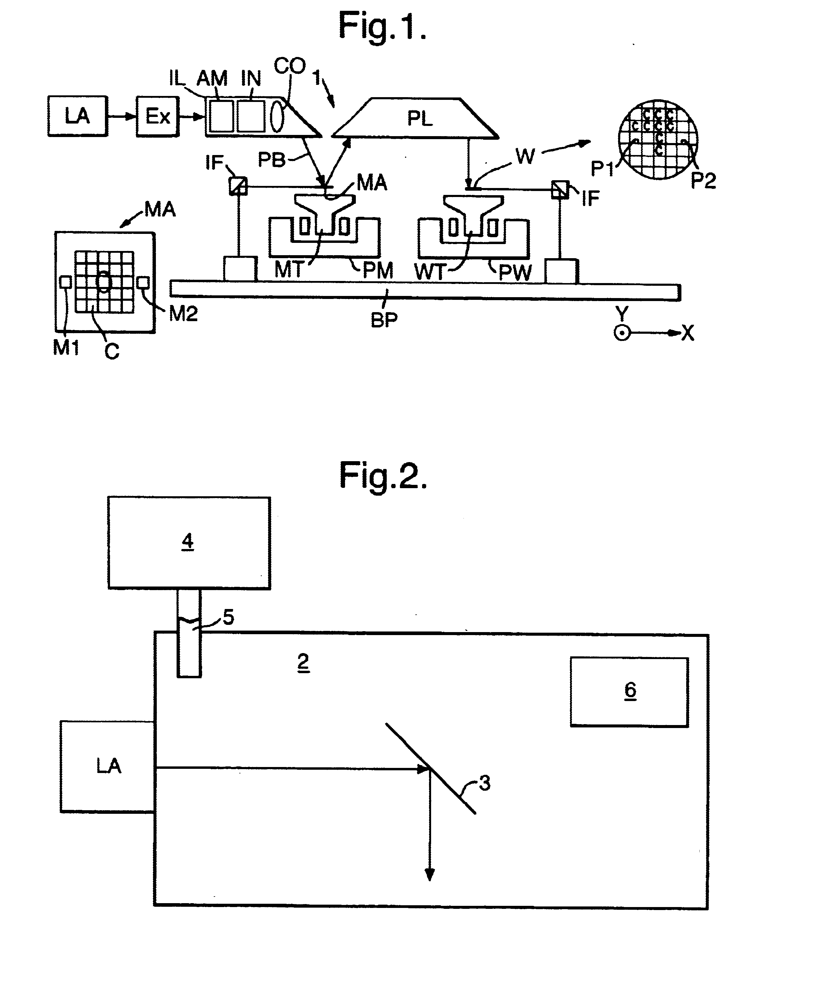
FIG. 1 schematically depicts a lithographic projection apparatus according to the invention. The apparatus includes:

a radiation system LA, IL for supplying a projection beam PB of UV or EUV radiation;

a first object table (mask table) MT for holding a mask MA (e.g. a reticle), and connected to first positioning means for accurately positioning the mask with respect to item PL;

a second object table (substrate or wafer table) WT for holding a substrate W (e.g. a resist-coated silicon wafer), and connected to second positioning means for accurately positioning the substrate with respect to item PL;

a projection system ("lens") PL (e.g. a mirror group) for imaging an irradiated portion of the mask MA onto an exposure area C of a substrate W held on the substrate table WT.

As here depicted, the apparatus is of a reflective type (i.e. has a reflective mask). However, in general, it may also be of a transmissive type, for example.

The radiation system may include a source LA (e.g. an Hg lamp, ...


PUM

PropertyMeasurementUnit
wavelengthaaaaaaaaaa
partial pressureaaaaaaaaaa
wavelengthsaaaaaaaaaa

Abstract

In-situ cleaning of optical components for use in a lithographic projection apparatus can be carried out by irradiating a space within the apparatus containing the optical component with UV or EUV radiation having a wavelength of less than 250 nm, in the presence of molecular oxygen. Generally, the space will be purged with an ozoneless purge gas which contains a small amount of molecular oxygen in addition to the usual purge gas composition. The technique can also be used in an evacuated space by introducing a low pressure of molecular oxygen into the space.

Description

1. Field of the InventionThe present invention relates generally to lithographic projection apparatus and more particularly to lithographic projection apparatus incorporating purge gas within the optical system.2. Background of the Related ArtIn general, lithographic apparatus such as are described herein include a radiation system for supplying a projection beam of electromagnetic radiation which may have a wavelength of 250 nm or less, for example. Such apparatus further generally include a support structure for supporting patterning structure which patterns the projection beam according to a desired pattern, a substrate table for holding a substrate and a projection system for projecting the patterned beam onto a target portion of the substrate.The term "patterning structure" as here employed should be broadly interpreted as referring to means that can be used to endow an incoming radiation beam with a patterned cross-section, corresponding to a pattern that is to be created in a...

Claims


Application Information

Patent Timeline
Patent Type & Authority Patents(United States)
IPC IPC(8): G03F7/20H01L21/027
CPCG03F7/70925G03F7/20
Inventor VAN SCHAIK, WILLEMDUISTERWINKEL, ANTONIE ELLERTMERTENS, BASTIAAN MATTHIASMEILING, HANSKOSTER, NORBERTUS BENEDICTUS
Owner ASML NETHERLANDS BV
Why Eureka
Try Eureka