Adjustable permanent magnet bias

a permanent magnet and bias technology, applied in the field of permanent magnets, can solve problems such as signal asymmetry, detection and tracking problems, and non-linear signaling, and achieve the effects of reducing the number of permanent magnets, and improving the accuracy of permanent magnets

Inactive Publication Date: 2004-04-20
SEAGATE TECH LLC
View PDF11 Cites 45 Cited by
  • Summary
  • Abstract
  • Description
  • Claims
  • Application Information

AI Technical Summary

Benefits of technology

In accordance with an additional aspect of the invention, a method of using a permanent magnet to generate a magnetic bias field in a read sensor having an air-bearing surface and an opposing top surface comprises establishing a magnetization in the permanent magnet, and positioning the permanent adjacent the top surface of the read sensor such that the magnetization of the permanent magnet is in a direction other than normal to the air-bearing surface of the read sensor. The method may a...

Problems solved by technology

If the sensor is, for example, either over or under biased, the signal will become non-linear and create a loss of amplitude, signal asymmetry and detection and tracking problems.
One difficult aspect of properly biasing...

Method used


Image

  • Adjustable permanent magnet bias
  • Adjustable permanent magnet bias
  • Adjustable permanent magnet bias

Examples


Embodiment Construction

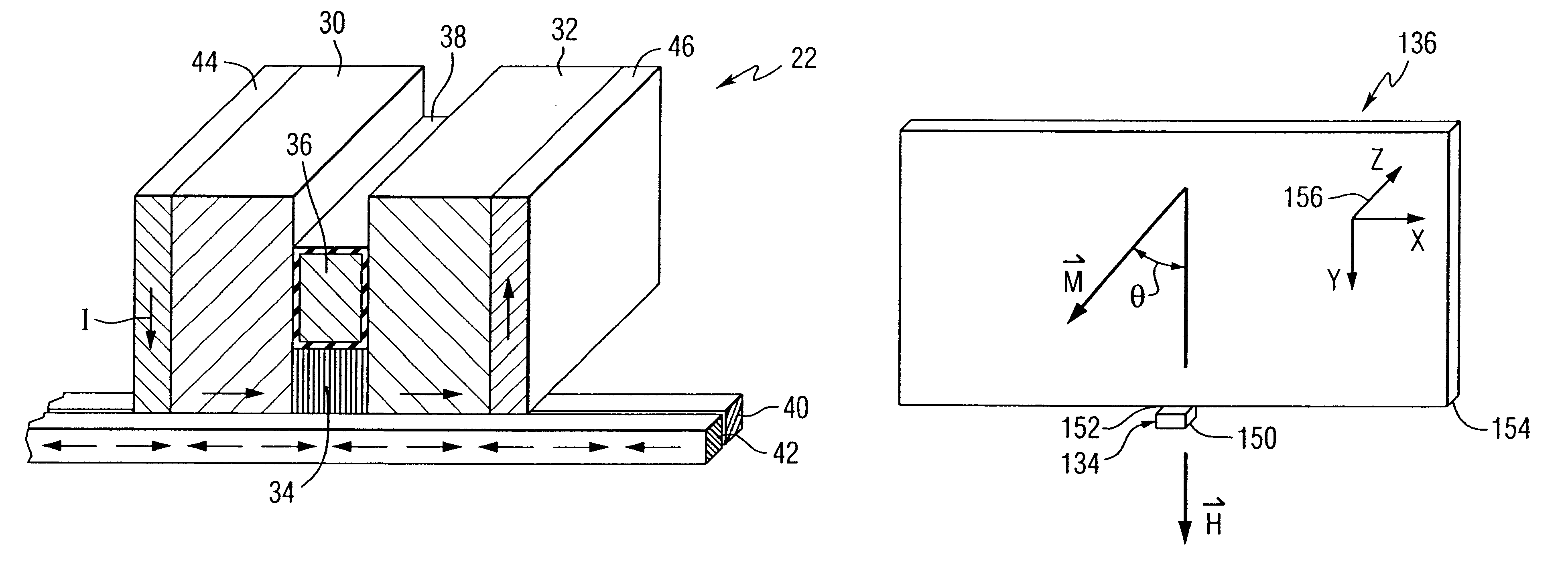
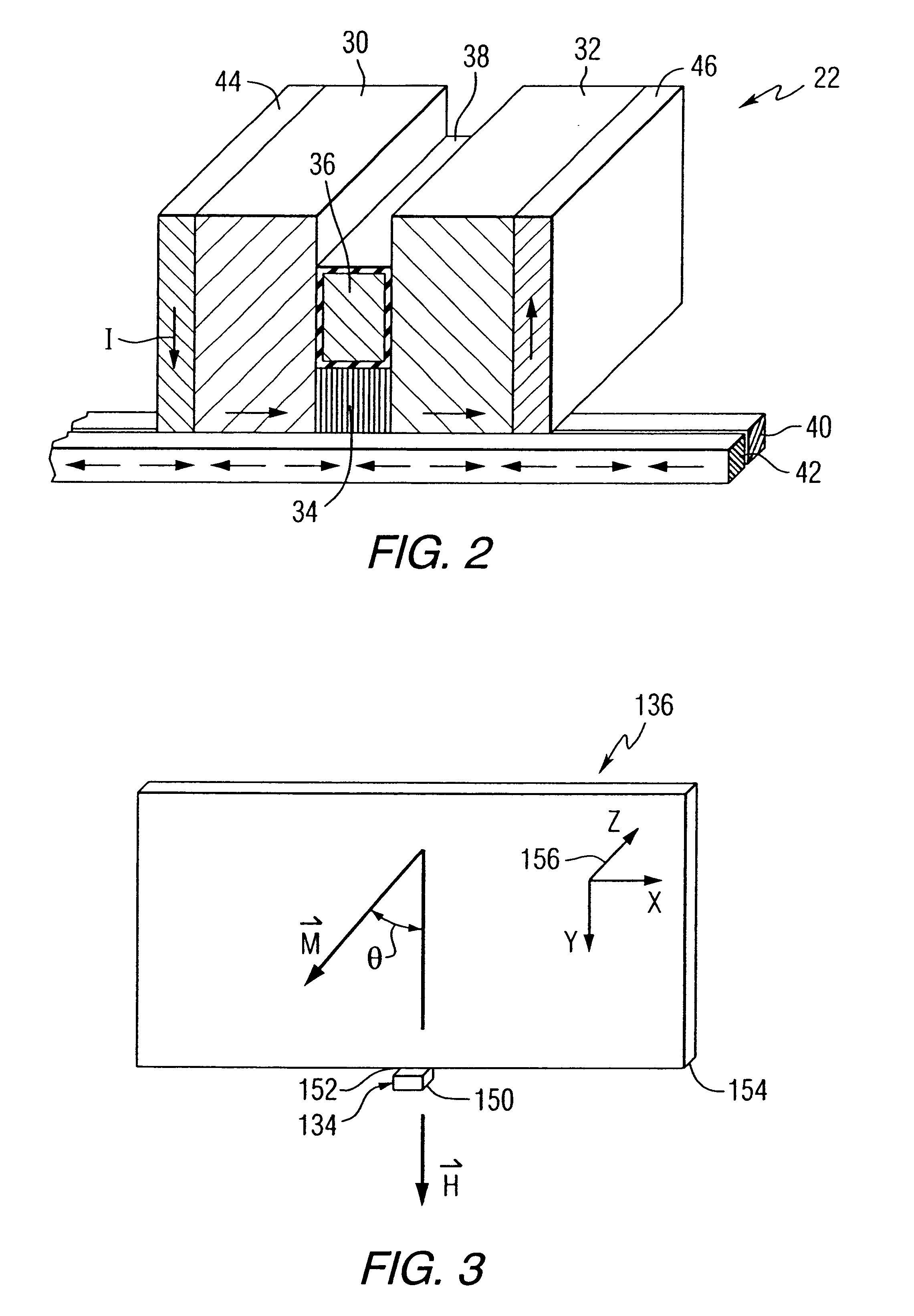
The invention provides an adjustable permanent magnet bias for a magnetic recording head, particularly suitable for use with a magnetic disc storage system. A recording head is defined as a head capable of performing read and / or write operations.

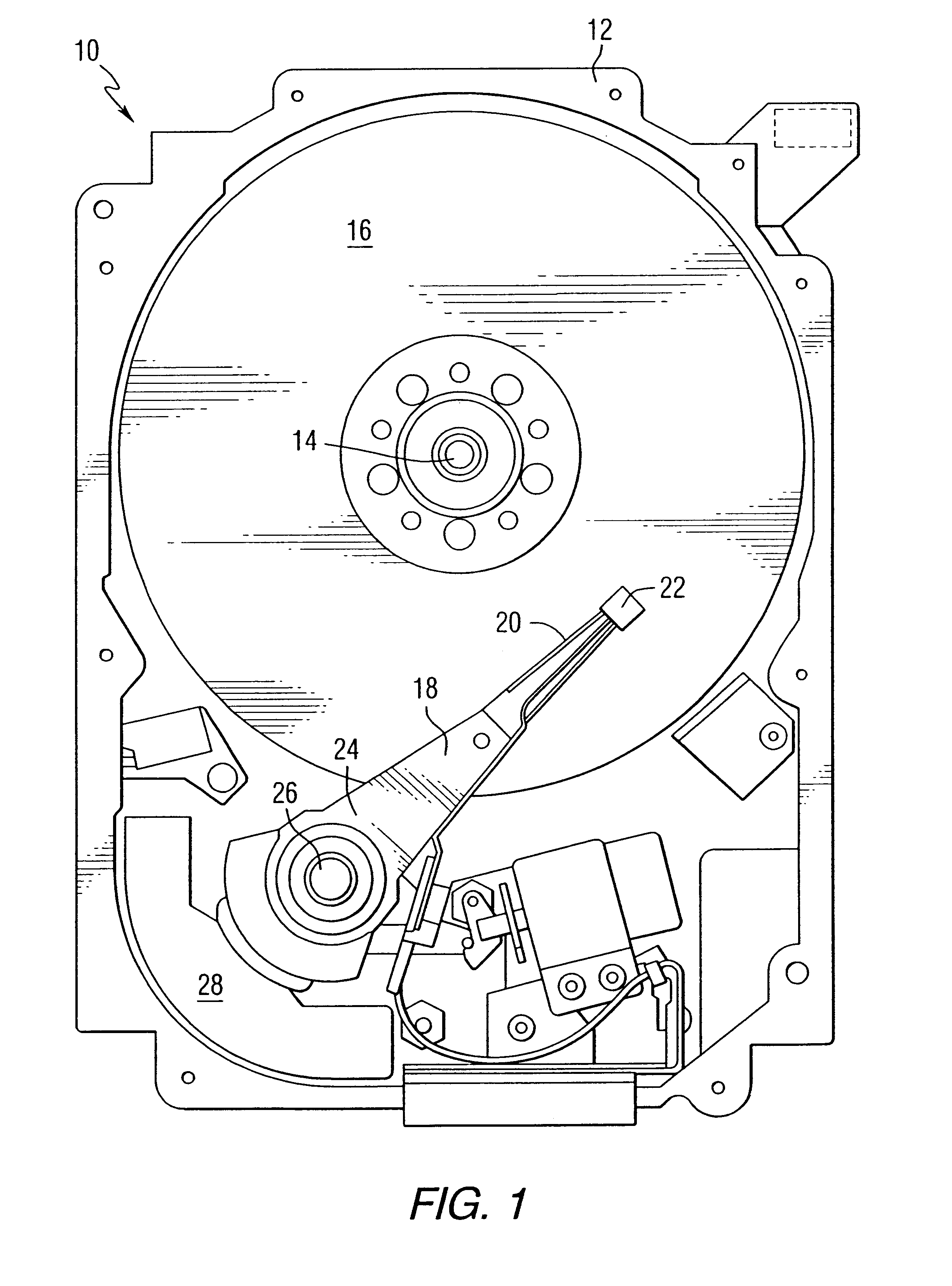
FIG. 1 is a pictorial representation of a disc drive 10 that can utilize the adjustable permanent magnet and read head constructed in accordance with this invention. The disc drive includes a housing 12 (with the upper portion removed and the lower portion visible in this view) sized and configured to contain the various components of the disc drive. The disc drive includes a spindle motor 14 for rotating at least one magnetic storage medium 16 within the housing, in this case a magnetic disc. At least one arm 18 is contained within the housing 12, with each arm 18 having a first end 20 with a recording and / or read head or slider 22, and a second end 24 pivotally mounted on a shaft by a bearing 26. An actuator motor 28 is located at the arm'...


PUM


Abstract

A read head, particularly suitable for a magnetic disc storage system, includes a read sensor having an air-bearing surface and an opposing top surface. The read head also includes a permanent magnet positioned adjacent the top surface of the read sensor for generating a magnetic bias field in the read sensor. The permanent magnet has a magnetization in a direction other than normal to the air-bearing surface of the read sensor.

Description

FIELD OF THE INVENTIONThe invention relates to magnetic recording heads, and more particularly, to a permanent magnet for generating a magnetic bias field in a read head of such recording heads.BACKGROUND OF THE INVENTIONDevices utilizing the giant magnetoresistance (GMR) effect have utility as magnetic sensors, especially as read sensors in read heads used in magnetic disc storage systems. The GMR effect is observed in thin, electrically conductive multi-layer systems having magnetic layers. In operation, a sense current is passed through the read head of the magnetic disc storage system. The presence of a magnetic field in the storage media adjacent to the sensor changes the resistance of the sensor. A resulting change in voltage drop across the sensor due to the change of the resistance of the sensor results in an output voltage that can be measured and used to recover magnetically stored information.The output voltage is affected by various characteristics of the sensor. The sen...

Claims


Application Information

Patent Timeline
IPC IPC(8): G11B5/39G11B5/48
CPCB82Y10/00B82Y25/00G11B5/3903G11B5/3932G11B5/488G11B2005/3996Y10S977/934
Inventor SEIGLER, MICHAEL ALLENPARKER, GREGORY JOHNVAN DER HEIJDEN, PETRUS ANTONIUS
Owner SEAGATE TECH LLC
Why Eureka
Try Eureka