

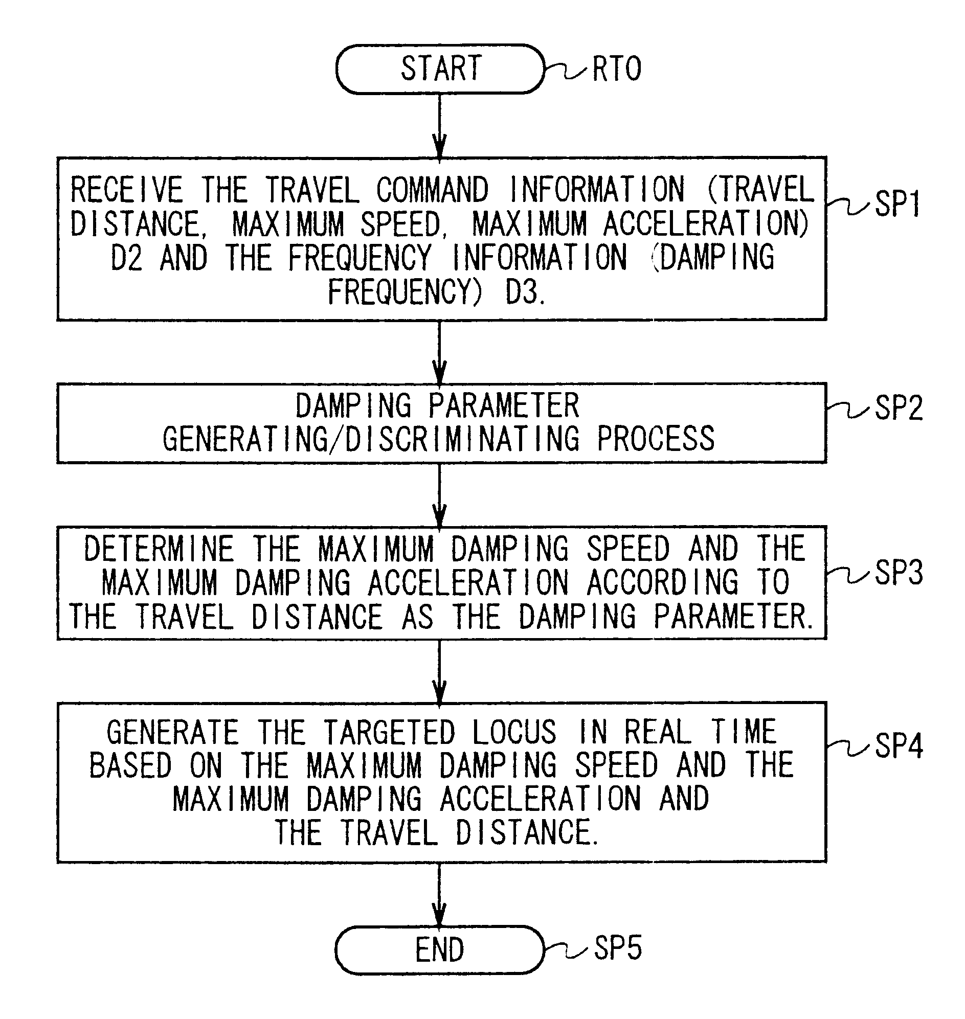
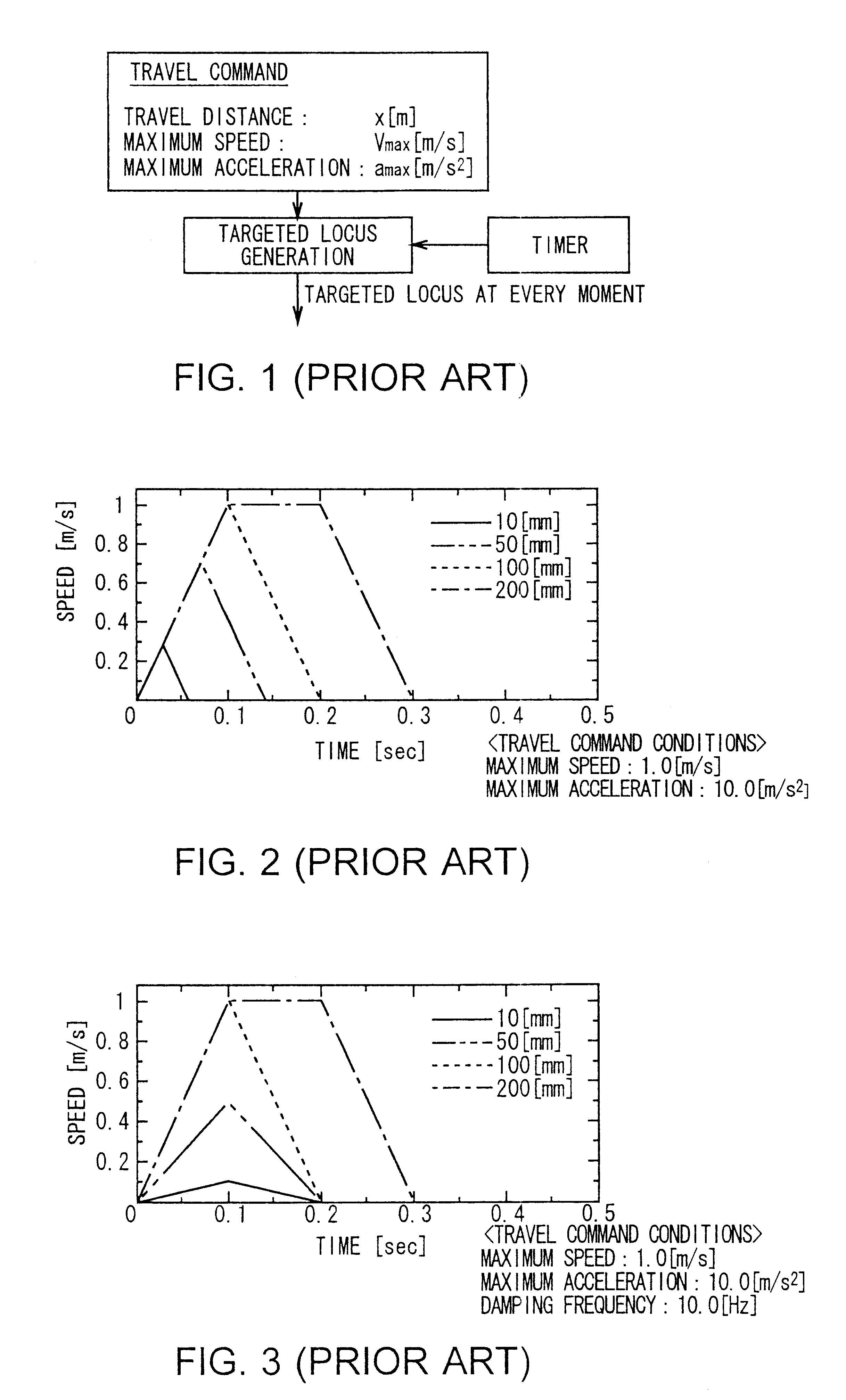
Positioning device and method
a technology of positioning device and positioning plate, which is applied in the direction of electric programme control, motor/generator/converter stopper, programme control, etc., can solve the problems of inability to make an even multiple of the vibration frequency, difficult to achieve high speed, and complex operation
- Summary
- Abstract
- Description
- Claims
- Application Information
AI Technical Summary
Benefits of technology
Problems solved by technology
Method used
Image

Examples
Embodiment Construction
Preferred embodiments of this invention will be described with reference to the accompanying drawings:
(1) Mounter Construction of this Embodiment
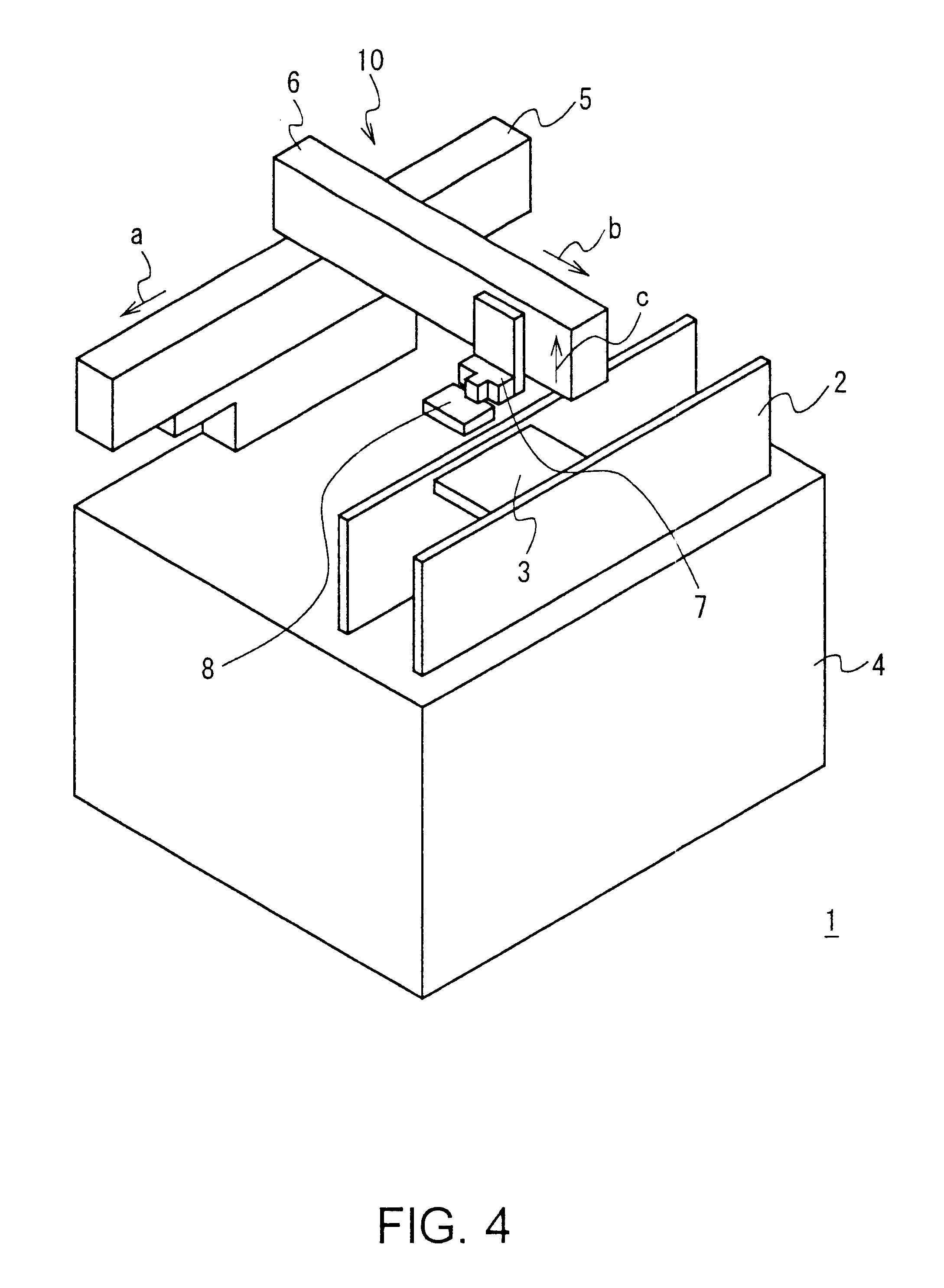
In FIG. 4, reference numeral 1 denotes a mounter as a whole according to this embodiment. The mounter 1 securely holds a substrate 3 of a work-piece at a predetermined position on a frame 4 for a certain time, the substrate 3 being carried to the predetermined position on the frame 4 by a substrate carrying portion 2.
On this frame 4, a head 8 is disposed via a first movable body 5 that is freely movable in a forward direction indicated by an arrow "a" relative to the frame 4 and in its opposite backward direction, a second movable body 6 that is freely movable in a right direction indicated by the arrow "b" relative to the first movable body 5 and in its opposite left direction, and a third movable body 7 that is freely movable in an upward direction indicated by the arrow "c" relative to the second movable body 6 and in its opposite downwa...
PUM
 Abstract
Description
Claims
Application Information