Variable geometry turbine

a turbine and variable geometry technology, applied in the direction of wind turbine control, liquid fuel engine, motor, etc., can solve the problems of nozzle seizing and detriment to the efficiency of the nozzl

Inactive Publication Date: 2004-04-27
FPT MOTORENFORSCHUNG
View PDF6 Cites 32 Cited by
  • Summary
  • Abstract
  • Description
  • Claims
  • Application Information

AI Technical Summary

Problems solved by technology

First, the vanes necessarily have to have a "straight" profile, i.e. constant in the axial direction, without any torsion or variation of pitch angle. If not, the axial movement of the vanes in the respective slots would be possible only by providing substantial play between the vanes and the slots, which would be detrimental to the efficiency of the nozzle.
In addition to the design limits discussed above, nozzles with straight vanes sliding in respective slots are subject to problems of seizing; in practice even small geometrical errors due to manufacturing tolerances or heat distortions during operation may cause the nozzle to seize.

Method used


Image

  • Variable geometry turbine
  • Variable geometry turbine
  • Variable geometry turbine

Examples


Embodiment Construction

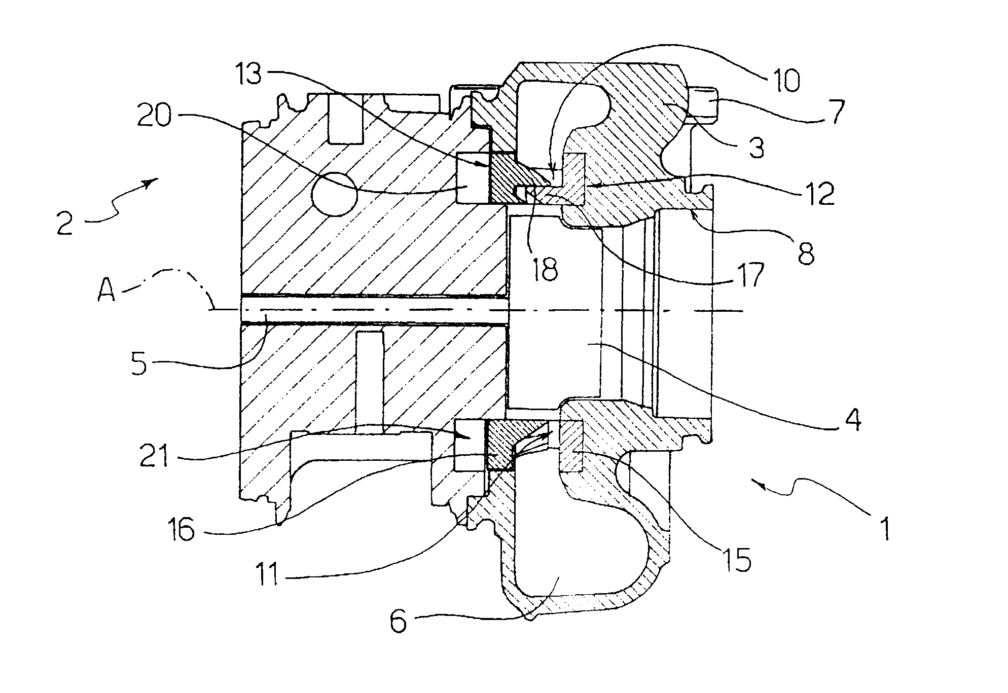
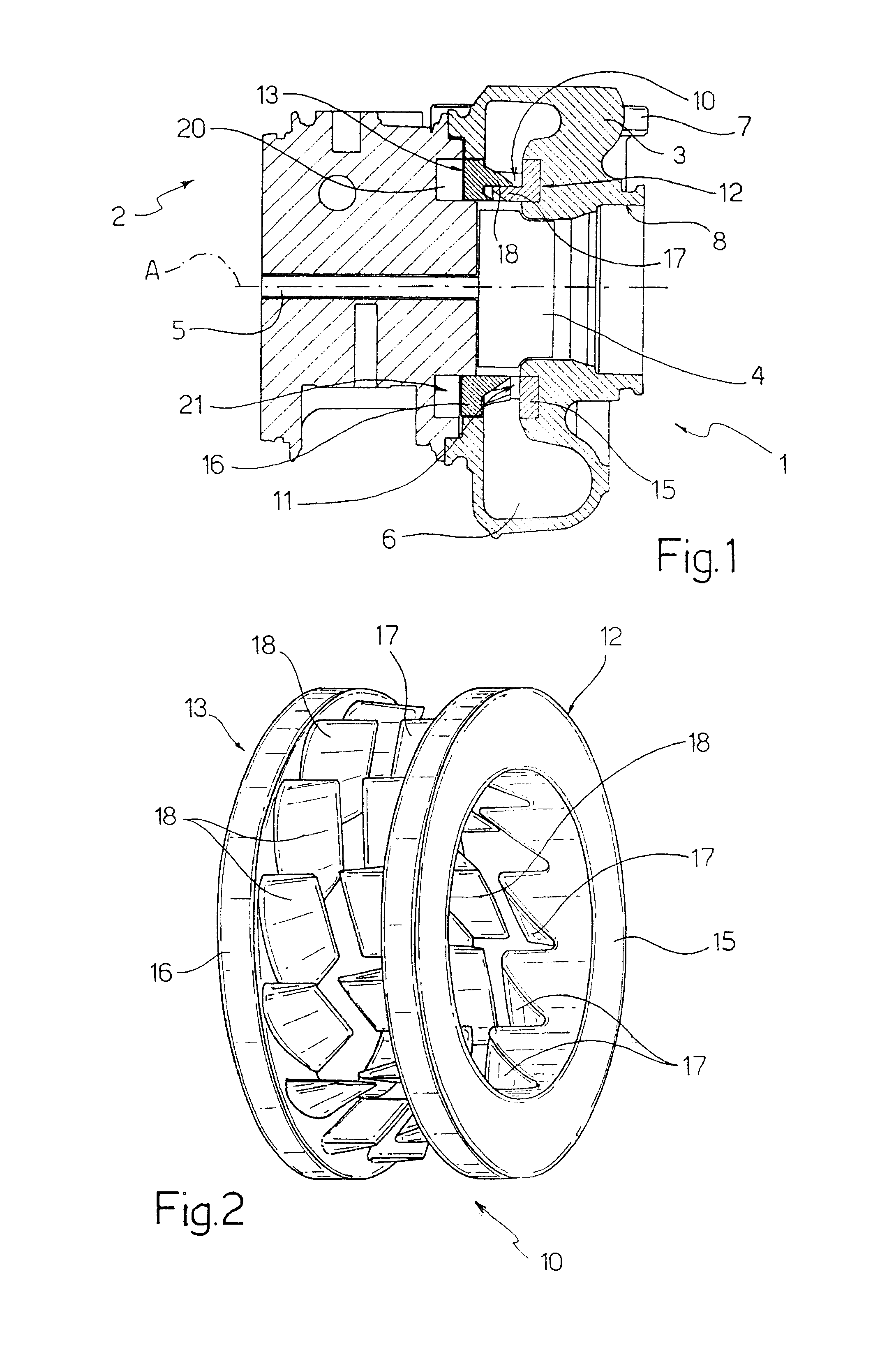
In FIG. 1, a variable geometry turbine is shown overall by 1; the turbine is advantageously used in a turbocompressor 2 (shown in part) for supercharging an internal combustion engine.

The turbine 1 essentially comprises a housing 3 and a rotor 4 of axis A supported in a rotary manner about the axis A and rigidly connected with a drive shaft 5 of a compressor (not shown). The housing 3 defines, in a known manner, a spiral inlet channel 6 surrounding the rotor 4 and provided with an inlet opening 7 adapted to be connected to an exhaust manifold (not shown) of the engine. The housing 3 further defines an axial outlet duct 8 for the exhaust gases at the outlet of the rotor 4.

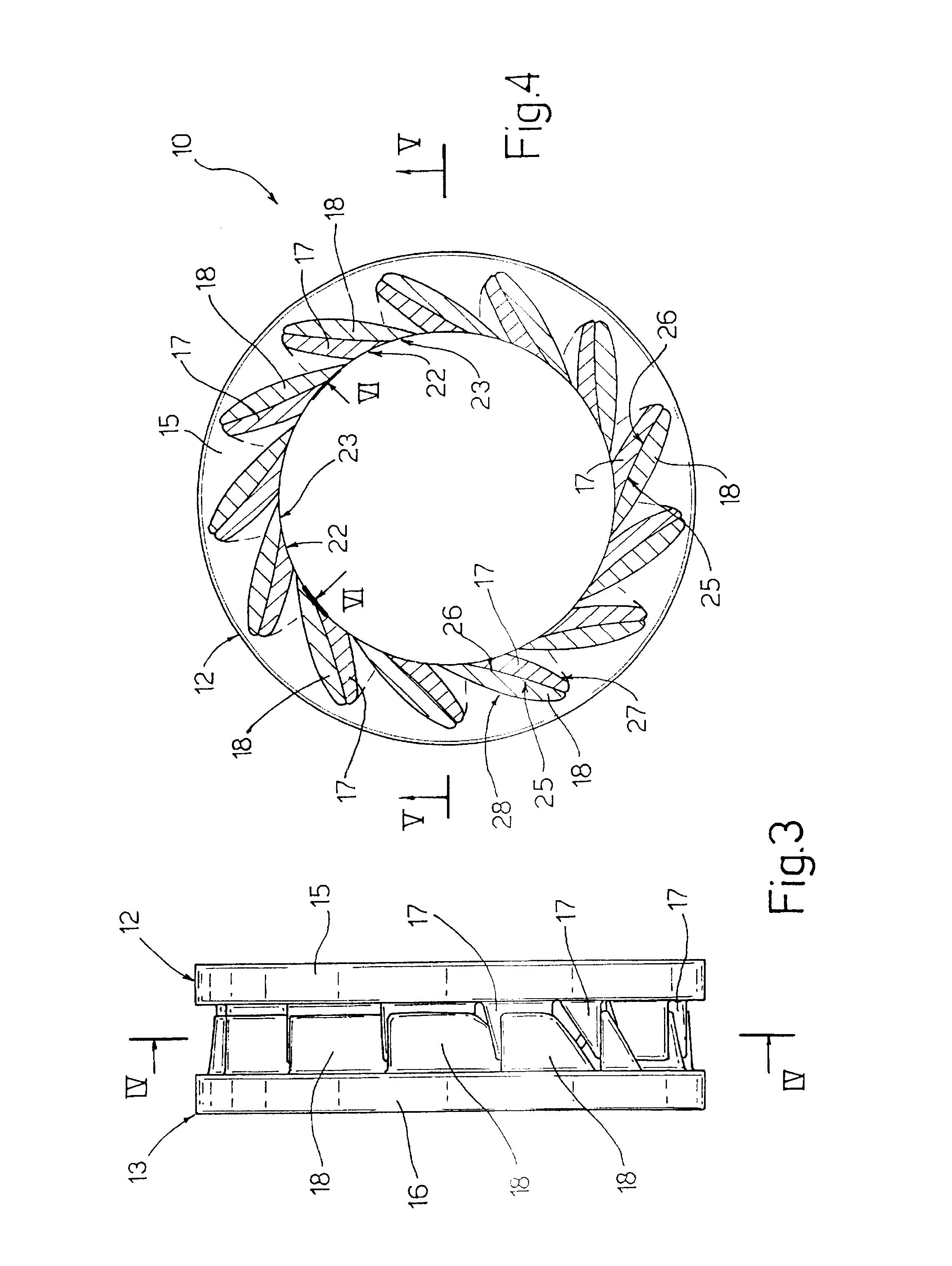
The turbine 1 lastly comprises a vaned annular nozzle 10 of variable geometry which is interposed radially between the inlet channel 6 and the rotor 4 and defines a throat section 11, i.e. a working section of minimum flow of the nozzle 10, which can be varied to control the flow of exhaust gases from the inlet chan...


PUM


Abstract

A variable geometry turbine, particularly for a supercharger turbocompressor of an internal combustion engine, comprising an outer housing forming a spiral inlet channel for an operating fluid, a rotor supported in a rotary manner in the housing, and an annular vaned nozzle of variable geometry interposed radially between the channel and the rotor; the nozzle comprises a pair of vaned rings facing one another and provided with respective pluralities of vanes tapered substantially as wedges and adapted to penetrate one another, one of which can move axially with respect to the other in order to define a variable throat section between these vaned rings.

Description

The present invention relates to a variable geometry turbine. The preferred, but not exclusive, field of application of the invention is in superchargers of internal combustion engines, to which reference will be made in the following description in a non-limiting manner.BACKGROUND OF THE INVENTIONTurbines are known that comprise a spiral inlet channel surrounding the rotor of the turbine and a vaned annular nozzle interposed radially between the inlet channel and the rotor. Variable geometry turbines (VGT) are also known in which the vaned annular nozzle has a variable configuration so that flow parameters of the operating fluid from the inlet channel to the rotor can be varied. According to a known embodiment, the variable geometry nozzle comprises an annular control member moving axially to vary the throat section, i.e. the working flow section, of this nozzle. This annular control member may be formed, for instance, by a vane support ring from which the vanes extend axially and ...

Claims


Application Information

Patent Timeline
Patent Type & Authority Patents(United States)
IPC IPC(8): F01D17/14F01D17/16F01D17/00F02B37/22
CPCF01D17/143F01D17/165
Inventor LUTZ, ERNST
Owner FPT MOTORENFORSCHUNG
Why Eureka
Try Eureka