
Self-healing ring network and a method for fault detection and rectifying

Inactive Publication Date: 2004-04-27
TELEFON AB LM ERICSSON (PUBL)
View PDF14 Cites 18 Cited by
  • Summary
  • Abstract
  • Description
  • Claims
  • Application Information

AI Technical Summary

Problems solved by technology

A drawback of such a network is that a break in the ring or a failure of a node would prevent any node upstream of the break / failure of communicating with any node downstream of the break.

Method used


Image

  • Self-healing ring network and a method for fault detection and rectifying
  • Self-healing ring network and a method for fault detection and rectifying
  • Self-healing ring network and a method for fault detection and rectifying

Examples


Embodiment Construction

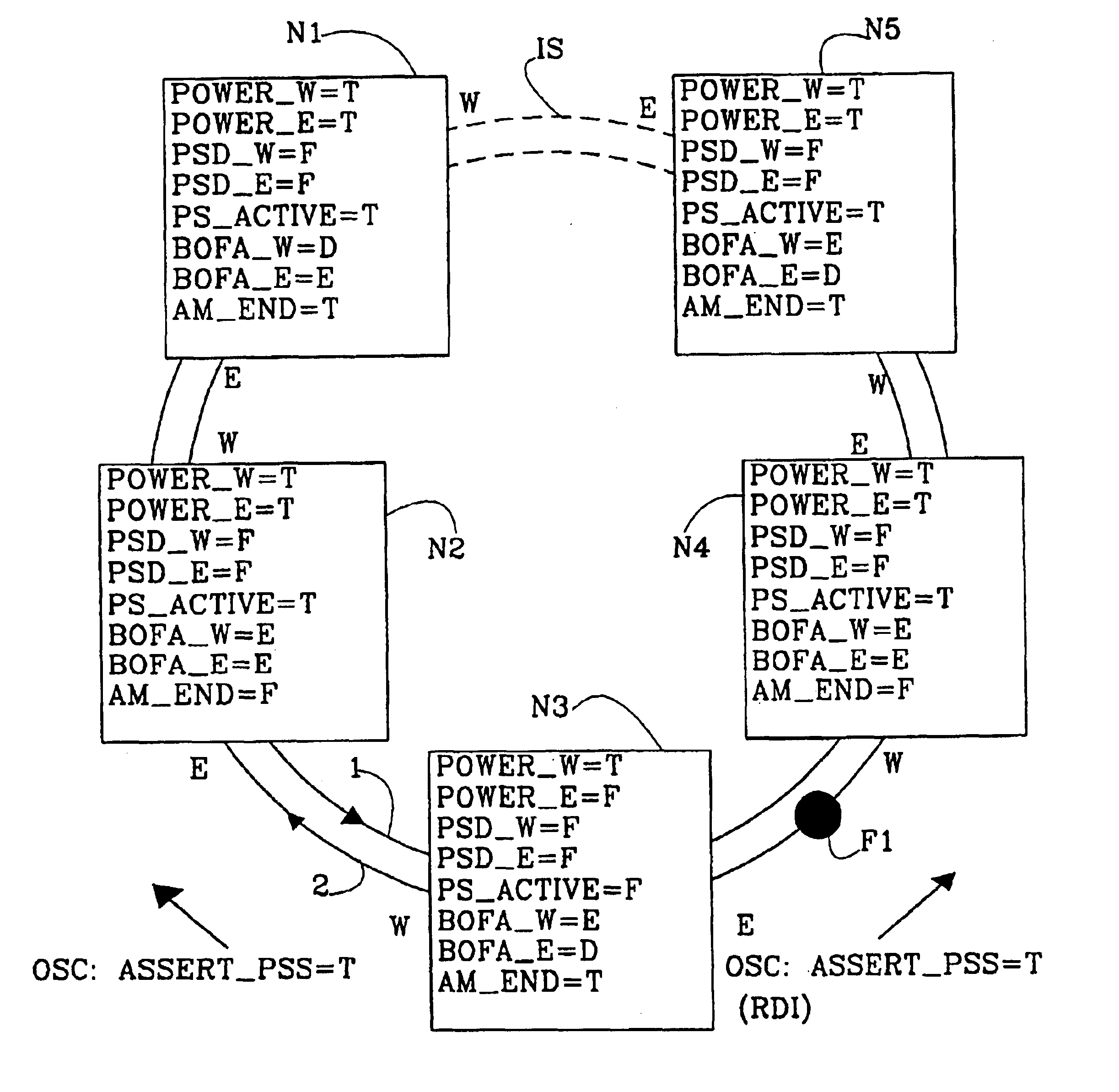
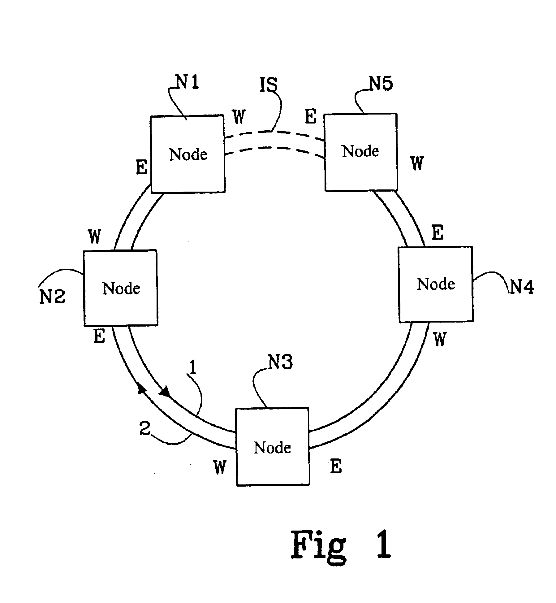
In FIG. 1 is shown an optical ring network using Wavelength Division Multiplexing, which will be called a "ring" for short. Five nodes N1, N2, N3, N4, N5 are connected to two optical fibres 1, 2 working in opposite directions, that is working as a bi-directional bus. Of course it is possible to have any number of nodes on the ring.

Data traffic and signalling from one node to another will be sent on both fibres 1, 2, that is in both directions.

However, between two of the nodes N1, N5, a segment of the ring, called an inactive segment IS, does not carry any data traffic, only signalling. This means that even though data traffic is sent on both fibres, a node will only receive data traffic from another node on one of the fibres. The nodes N1, N5 closest to the inactive segment IS will work as end-nodes. If a fault occurs in a segment on the ring that is not the inactive segment, then the inactive segment will be moved to encompass the fault.

The place where traffic enters the node from ...


PUM


Abstract

The present invention relates to a self-healing ring network and a method for fault handling in said network. Said network comprises two communication paths (1, 2) and at least two nodes (N1, N2, N3, N4, N5). A first node (N1) and a second node (N5) suppress transmission to and / or reception from a segment (IS) in the ring, called an inactive segment. In the case of an occurring fault, the inactive segment is moved to the fault. According to the invention the network comprises a separate supervisory channel (OSC) for transmitting information of the fault between the nodes (N1, N2, N3, N4, N5) of the network, in which supervisory channel (OSC) a fault flag (ASSERT_PSS) is provided for the indication of the fault.

Description

The present invention relates to a self-healing ring network and a method for fault detection and rectifying in said network.DESCRIPTION OF RELATED ARTWave Division Multiplexing (WDM) is a technology allowing the transmission of a number of optical signals through an optical fibre using different separated light wavelengths. In this way the information carrying capacity may be increased significantly. The capacity depends on the number of used wavelength channels and their bandwidth. The signal at each wavelength travels through the fibre irrespectively of the other signals, so that each signal represents a discrete channel with large bandwidth.A ring communication network is made up of nodes that are connected in tandem in a ring by a unidirectional communication path, such as an optical fibre. A node receives transmissions from an upstream node. The return traffic is transmitted downstream to the first nodeA drawback of such a network is that a break in the ring or a failure of a ...

Claims


Application Information

Patent Timeline
Patent Type & Authority Patents(United States)
IPC IPC(8): H04J14/02H04L12/437
CPCH04J14/0227H04J14/0283H04J14/0289H04L12/437H04J14/0241
Inventor ASKINGER, TOMASJOHANSSON, BENGTWOOD, NIGEL
Owner TELEFON AB LM ERICSSON (PUBL)
Learn More