Substation locking mechanism

A locking mechanism and substation technology, which is applied to electrical components, circuit devices, panel/switch station circuit devices, etc., can solve problems such as bus ground faults, poor robustness, and bus methods that are not suitable for outdoor installation and deployment.

Active Publication Date: 2018-03-02
ZHUHAI UNITECH POWER TECH CO LTD
View PDF5 Cites 0 Cited by
  • Summary
  • Abstract
  • Description
  • Claims
  • Application Information

AI Technical Summary

Problems solved by technology

[0008] 1) The bus provides power to drive the remote control locking relay, usually a DC power supply, and the resulting bus has the risk of ground fault;
[0009] 2) The electromagnetic compatibility immunity of the data bus is relatively poor, especially the single-bus mode shared with the power bus;
[0010] 3) The bus mode is not suitable for outdoor installation and deployment;
[0011] 4) The robustness is relatively poor. If a node on the bus is disconnected, the equipment behind the node will fail
[0013] Although this method is simple and easy to use, each distributed node is relatively independent, but in the project implementation, most of the intelligent devices at the process layer use optical fiber communication networking, therefore, each independent node will occupy an optical fiber communication port on the network switch
It can be seen that using this method will require more fiber optic interactive machines, and the cost will be relatively high

Method used


Image

  • Substation locking mechanism
  • Substation locking mechanism
  • Substation locking mechanism

Examples


Embodiment

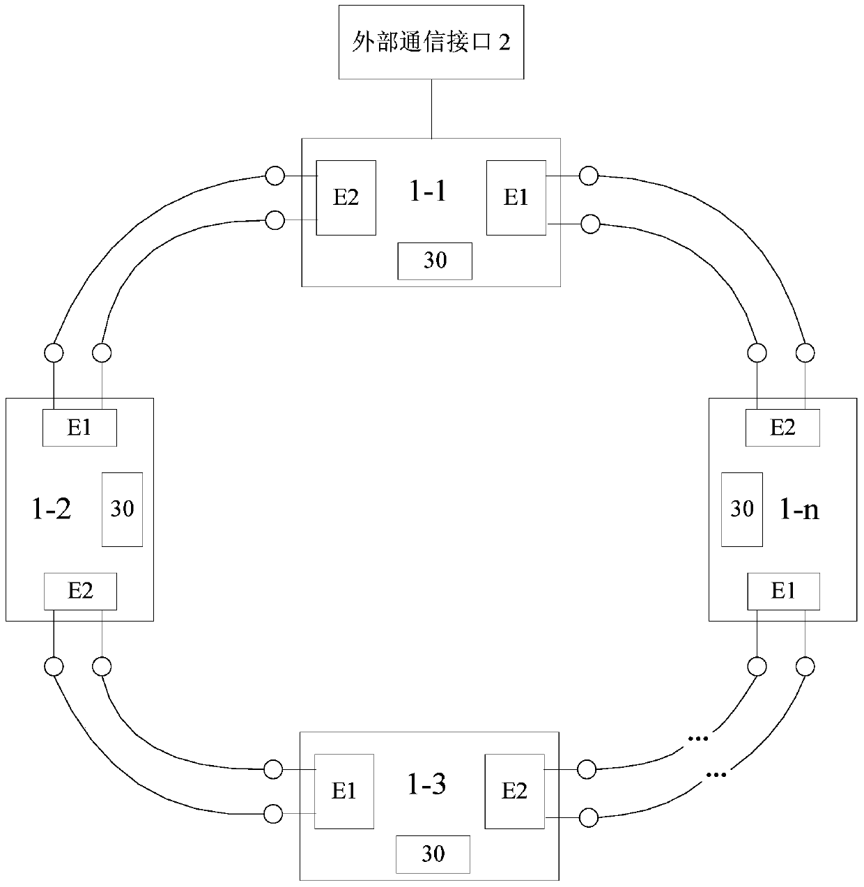
[0035] In order to solve the problems of the prior art, this embodiment proposes a substation locking mechanism, see figure 1 , is an annular locking mechanism; the annular locking mechanism includes a group of intelligent locking units (the first intelligent locking unit 1-1, the second intelligent locking unit 1-2, ..., the Nth intelligent locking unit 1-n) and an external communication unit.

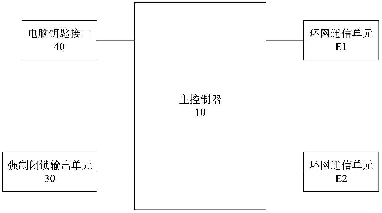
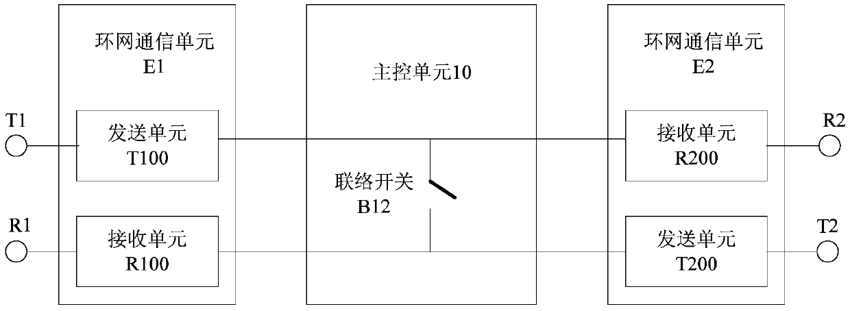
[0036] See figure 2As shown, the intelligent locking unit includes a main control unit 10 , two ring network communication units (the first ring network communication unit E1 and the second ring network communication unit E2 ), and a forced locking output unit 30 . The connection mode of the intelligent locking unit is as follows: the main control unit is respectively connected to two ring network communication units (E1, E2) and the forced locking output unit.

[0037] In addition, the intelligent locking unit also includes a computer key interface 40 for interacting with the comp...


PUM


Abstract

The invention provides a substation locking mechanism, including: a plurality of intelligent locking units and an external communication unit; the intelligent locking unit includes a main control unit, a first ring network communication unit, a second ring network communication unit and a forced locking output unit; The connection relationship of two intelligent locking units is: the second ring network communication unit of the first intelligent locking unit is connected to the first ring network communication unit of the second intelligent locking unit, and the second ring network communication unit of the second intelligent locking unit is connected to the third The first ring network communication unit of the intelligent locking unit, ..., the second ring network communication unit of the Nth intelligent locking unit is connected to the first ring network communication unit of the first intelligent locking unit to form a closed ring connection. The locking mechanism of the substation is a dual-ring network redundant operation in normal working state. When a node is abnormal, it can be transformed into two independent ring networks to continue to operate, which can realize the self-healing of the ring network, taking into account the stability and reliability of the product operation. sex.

Description

technical field [0001] The invention relates to the technical field of substation automation equipment, in particular to a substation locking mechanism for a substation microcomputer to prevent electrical equipment from operating the system incorrectly. Background technique [0002] The microcomputer prevents electrical misoperation is a system in the field of substation technology. It is a system that uses computer, measurement and control, and communication technologies to prevent electrical misoperation of high-voltage electrical equipment and its auxiliary devices. It is mainly composed of the anti-misoperation host , analog terminal, computer key, communication device, mechanical coding lock, electrical coding lock, grounding lock and remote locking device and other components. [0003] In this system, mandatory locking refers to connecting contacts or locks controlled by the anti-malfunction host in series in the electric operation control circuit of electrical equipme...

Claims


Application Information

Patent Timeline
Patent Type & Authority Patents(China)
IPC IPC(8): H02J13/00H02B1/24
Inventor 陈雷岑积利杨海涛杨冬茜田克岩李根元
Owner ZHUHAI UNITECH POWER TECH CO LTD
Why Eureka
Try Eureka