3-point radial artery pressure pulse wave transducer using pneumatic system

Inactive Publication Date: 2004-05-04
GWANGJU INST OF SCI & TECH
View PDF5 Cites 12 Cited by
  • Summary
  • Abstract
  • Description
  • Claims
  • Application Information

AI Technical Summary

Benefits of technology

It is therefore the object of the present invention to provide a pressure pulse wave transducer that assures an accurate 3-point measurement method by using a pneumatic system that applies a uniform pressure at a given sensing point.

Problems solved by technology

However, none of the devices using the three-point measurement system is reliable because there have been mechanical problems due to the non-uniform measuring conditions at the three points.

Method used


Image

  • 3-point radial artery pressure pulse wave transducer using pneumatic system
  • 3-point radial artery pressure pulse wave transducer using pneumatic system
  • 3-point radial artery pressure pulse wave transducer using pneumatic system

Examples


Embodiment Construction

The present invention will be described in detail by way of the preferred embodiments with reference to the accompanying drawings.

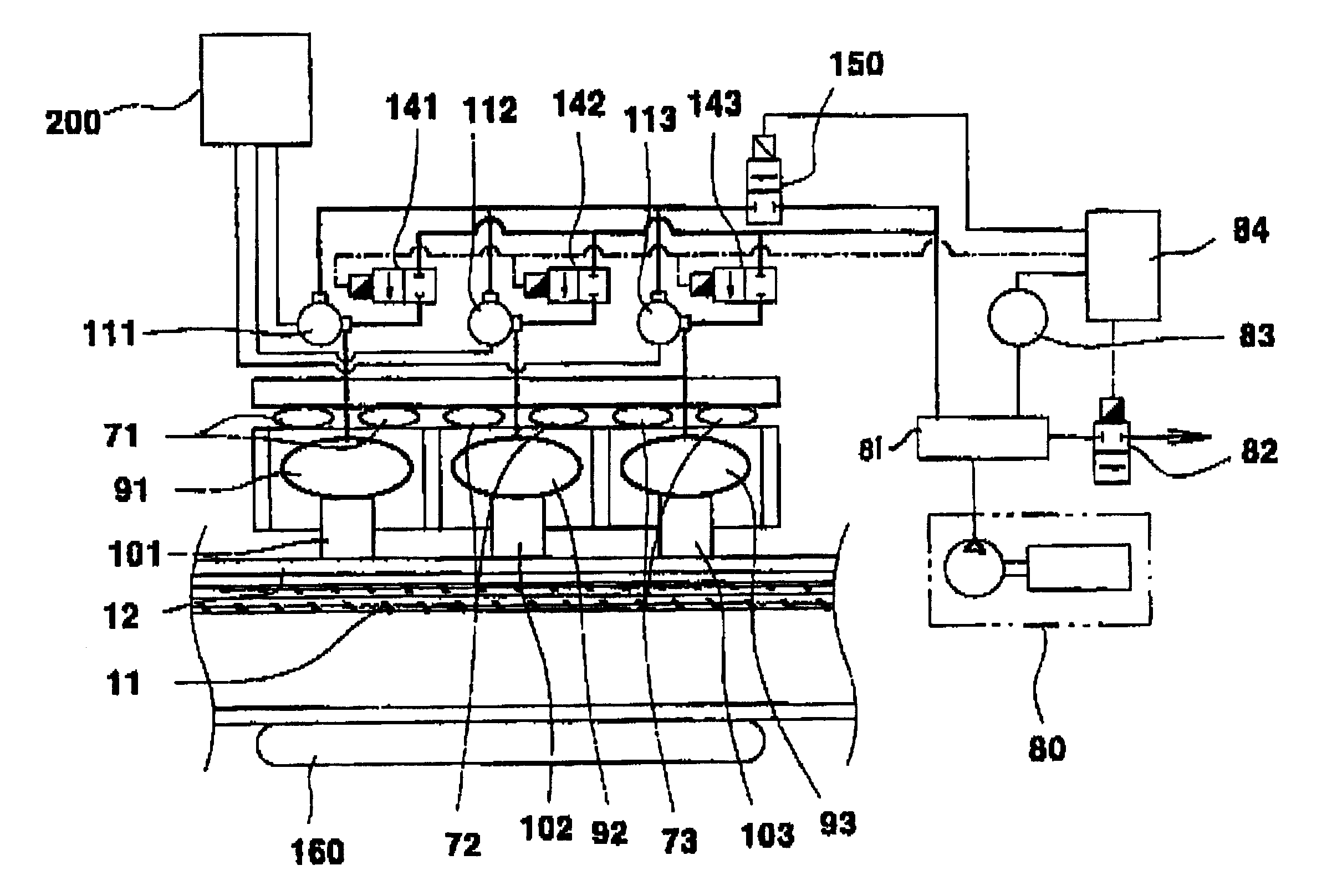
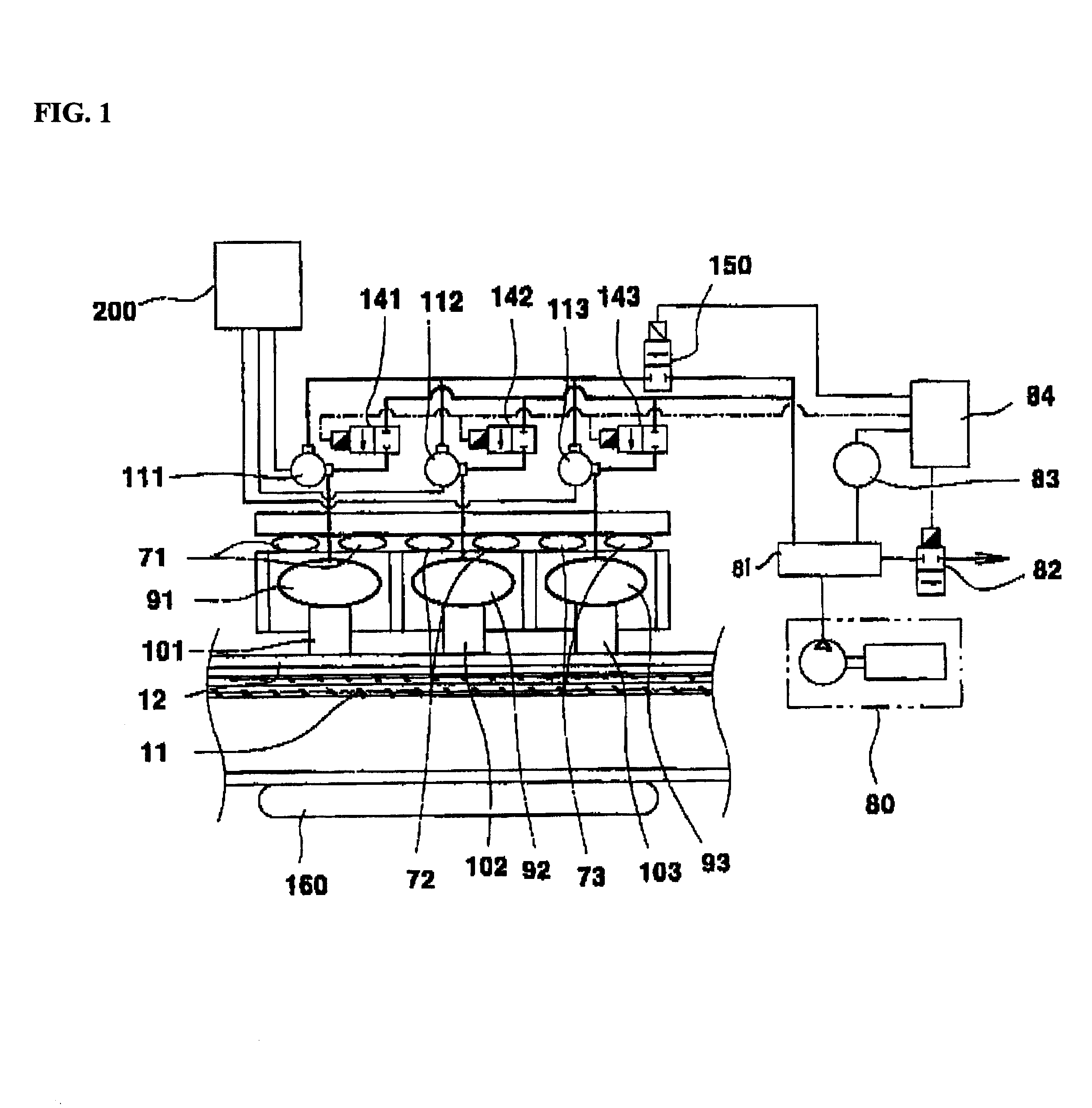
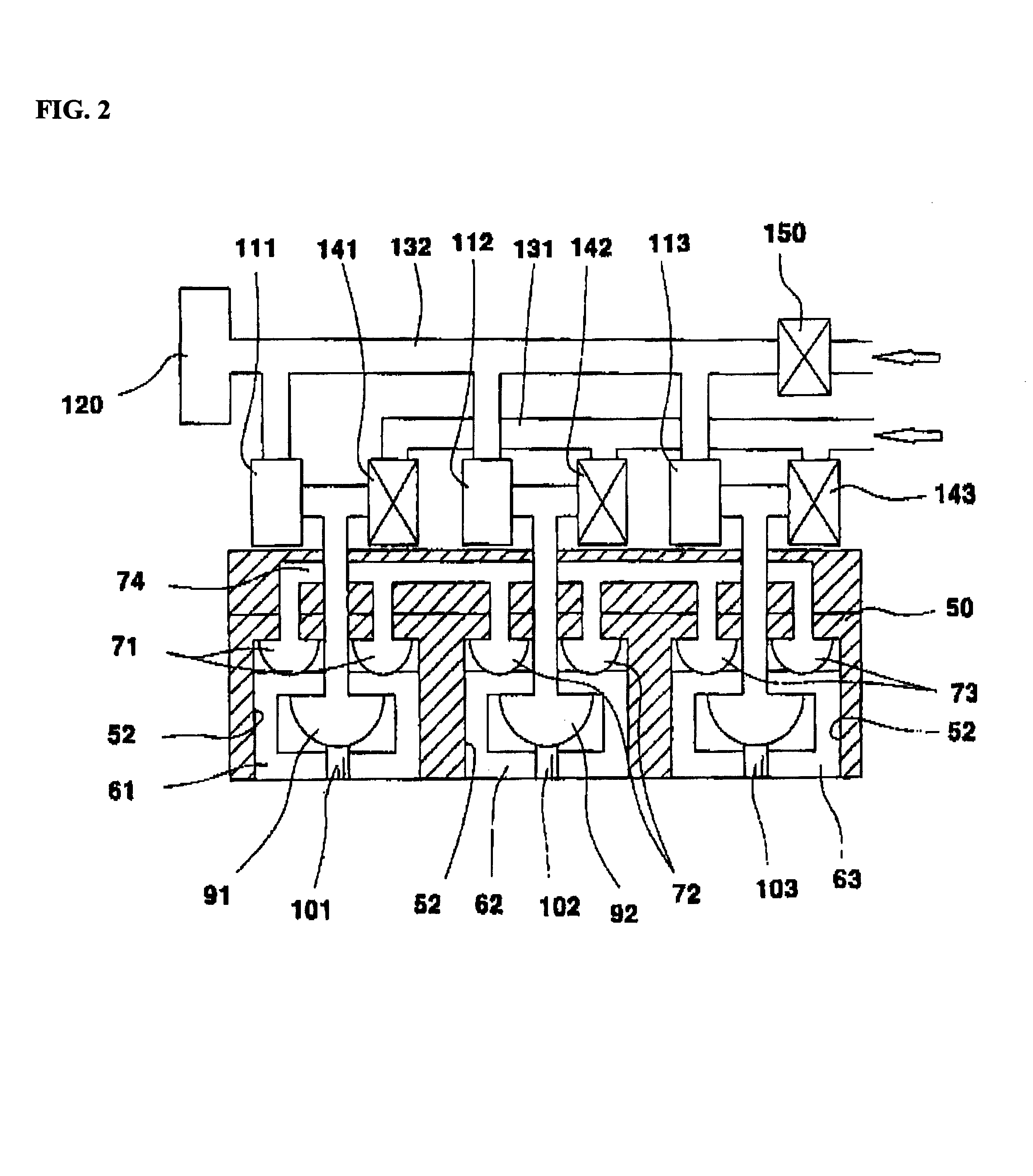
FIG. 1 is a construction of the entire system of a radial artery pressure pulse wave transducer according to the present invention; FIG. 2 is a longitudinal cross-sectional view of the pressure pulse wave transducer according to the present invention; and FIG. 3 is a horizontal cross-sectional view of the radial artery pressure pulse wave transducer.

As shown in FIGS. 1, 2 and 3, reference numeral 50 indicates a measurement device body. The body 50 has a wrist insertion space 51 into which a wrist 10 is sufficiently inserted in a longitudinal direction, as shown in FIG. 3.

Three depressing frames, 61, 62 and 63, are continuously isolated in a longitudinal direction along the internal top of the body 50. The depressing frames 61, 62 and 63 are installed to move up and down relative to the body 50, and are in contact with the skin 12 of the wrist 10. The depr...


PUM


Abstract

The present invention relates to a pressure pulse wave transducer for sensing change of the blood pressure in vivo and for converting it into an electrical signal to detect the arterial pressure pulse wave.

Description

1. FIELD OF THE INVENTIONThe present invention generally relates to a radial artery pressure pulse wave transducer for sensing a change in the pressure of the blood vessels in vivo, and converting the sensed result into an electrical signal to detect a pressure pulse wave. Specifically, the invention relates to a device for equal pressure distribution at given sensing points by using a pneumatic system for improved tightness and simultaneous conversion of force transferred through an air medium into an electrical signal to detect the pressure pulse wave.2. DESCRIPTION OF THE PRIOR ARTBlood pressure is measured to diagnose human body condition so that a medical practitioner can determine whether or not an individual has a cardiovascular-related disease.There is a conventional blood pressure measuring system which employs a method by which an electronic sensor such as a piezoelectric device, etc., directly contacts the human body to measure a change in the pressure within the blood ve...

Claims


Application Information

Patent Timeline
IPC IPC(8): A61B5/022A61B5/02
CPCA61B5/02233A61B5/02
Inventor LEE, SUN KYULEE, JONG JINAHAN, BYUNG HAPARK, PYONG WOON
Owner GWANGJU INST OF SCI & TECH
Why Eureka
Try Eureka