Land grid array connector having movable engagement of electrical contacts thereinto

a technology of land grid array and connector, which is applied in the direction of fixed connections, electrical apparatus construction details, and support structure mounting, etc., can solve the problem of liable accidental damage of contact portions 621

Inactive Publication Date: 2004-05-04
HON HAI PRECISION IND CO LTD
View PDF5 Cites 25 Cited by
  • Summary
  • Abstract
  • Description
  • Claims
  • Application Information

AI Technical Summary

Problems solved by technology

Therefore, the contact portions 621 are liable to be accidental

Method used


Image

  • Land grid array connector having movable engagement of electrical contacts thereinto
  • Land grid array connector having movable engagement of electrical contacts thereinto
  • Land grid array connector having movable engagement of electrical contacts thereinto

Examples


Embodiment Construction

Reference will now be made to the drawings to describe the present invention in detail.

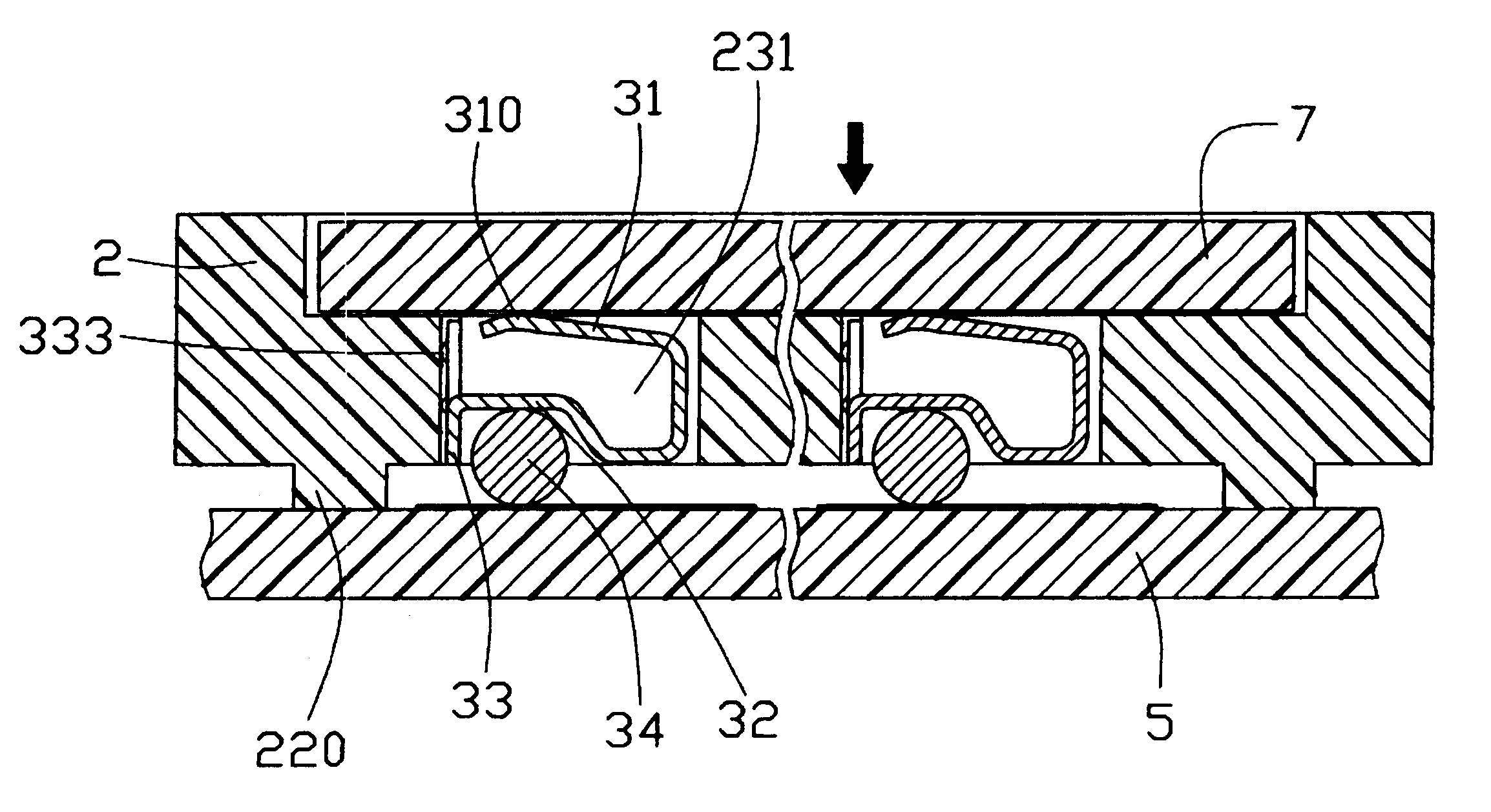
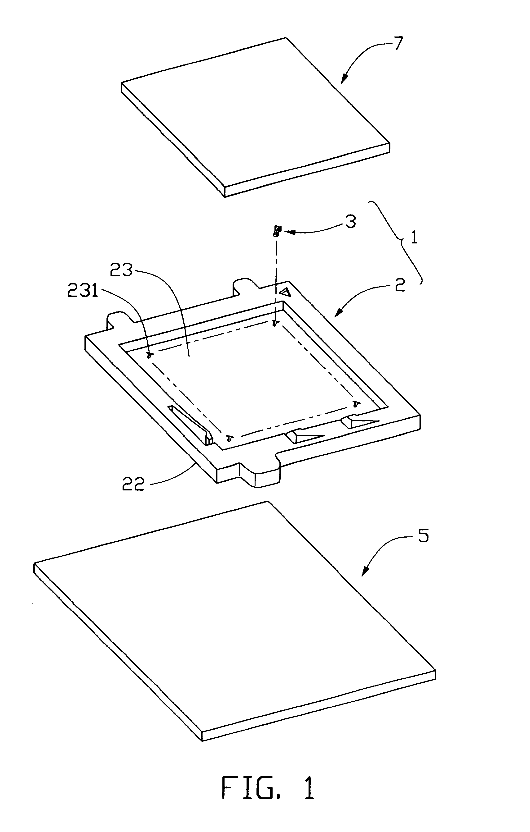
Referring to FIG. 1, a land grid array (LGA) connector 1 of the present invention is used for electrically connecting an electronic package such as an LGA central processing unit (CPU) 7 with a circuit substrate such as a printed circuit board (PCB) 5.

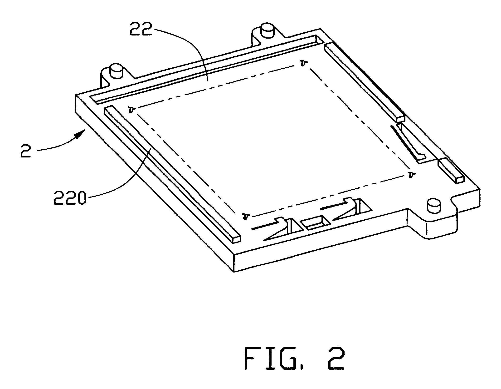
Also referring to FIGS. 2 through 5, the LGA connector 1 comprises an insulative housing 2, and a multiplicity of electrical contacts 3 received in the housing 2. The housing 2 is substantially rectangular, and defines a rectangular cavity 23 in a middle thereof and a multiplicity of passageways 231 in a portion thereof under the cavity 23. Each passageway 231 includes a slot 2312 at an end thereof. Three stand-offs 220 are formed at two opposite sides of a bottom surface 22 of the housing 2. Two aligned of the stand-offs 220 at one side of the bottom surface 22 are parallel to another of the stand-offs 220 at the opposite side of the bottom surface ...


PUM


Abstract

An LGA connector (1) includes a housing (2), and a number of contacts (3) received in the housing. The housing defines a cavity (23) in a middle thereof for receiving a CPU (7) and a multiplicity of passageways (231) in a portion thereof under the cavity, and has a number of stand-offs (220) at a bottom surface thereof. Each passageway includes a slot (2312). Each contact comprises an engaging portion (33) movably engaging in the corresponding slot, a long arm (31) accommodated within the passageway, and a solder portion (32) engaging a PCB (5). In use, the CPU is pressed downwardly to press the housing downwardly. The engaging portion of each contact slides upwardly in the slot. The stand-offs of the housing attach on the PCB, and the long arm of each contact deforms elastically to contact the CPU. The LGA connector thus electrically connects the CPU with the PCB.

Description

1. Field of the InventionThe present invention relates to land grid array (LGA) connectors, and particularly to an LGA connector for electrically connecting an electronic package such as an LGA central processing unit (CPU) with a circuit substrate such as a printed circuit board (PCB), wherein the LGA connector movably engages a number of electrical contacts therein.2. Description of the Prior ArtAt present, LGA connectors are widely used to electrically connect LGA CPUs with PCBs. A typical LGA connector is disclosed in Taiwan Patent No. 444960. Referring to FIGS. 8 through 10, a conventional LGA connector 6 comprises an insulative housing 61, and a multiplicity of electrical contacts 62 received in the housing 61. The housing 61 is substantially rectangular, and defines a rectangular cavity 63 in a middle thereof for receiving an LGA CPU 8 therein. A portion of the housing 61 under the cavity 63 defines a multiplicity of passageways 631 therethrough. Each passageway 631 includes ...

Claims


Application Information

Patent Timeline
IPC IPC(8): H05K7/10
CPCH01R12/57H05K7/1069
Inventor MA, HAO-YUN
Owner HON HAI PRECISION IND CO LTD
Why Eureka
Try Eureka