Current Sensor

a current sensor and sensor technology, applied in the field of current sensors, can solve the problems of sensor being sensitive to uniform magnetic, unable to provide simultaneously all the characteristics, and unable to achieve the effect of uniform magnetic field,

Inactive Publication Date: 2004-05-11
COLBY EDWARD GRELLIER
View PDF8 Cites 50 Cited by
  • Summary
  • Abstract
  • Description
  • Claims
  • Application Information

AI Technical Summary

Benefits of technology

Preferably, the one or more conductive paths are disposed to couple their magnetic fields generated in response to the one or more currents flowing therethrough preferentially to a subset of the zones, thereby generating a residual signal indicative of the magnitude of the one or more currents, the residual signal for use in providing the current measure. Preferentially coupling to a subset of the zones is of advantage in that the zones can be arranged to provide a substantially negligible response to uniform magnetic fields generated by sources remote to the sensor to render the sensor substantially insensitive to such uniform fields, whilst providing measuring sensitivity by virtue of preferentially coupling magnetic fields generated by the one or more currents to the subset of zones.
Alternatively, the meter is preferably implemented as a three-phase meter and is provided with two current sensors and means for deriving a third phase current by way of performing a simultaneous equation solution to signals derived from said two current sensors. By using the solution, for example based on Blondel's theorem, it is possible to reduce the number of current sensors required and thereby render the meter less expensive to manufacture, simpler in construction and more compact.

Problems solved by technology

Current sensors described in the aforesaid PCT applications and US patent are not capable of providing simultaneously all the characteristics (a) to (d) above.
Especially when the sensor is implemented comprising a stack of elongate coil elements, there is tendency for the sensor to become sensitive to uniform magnetic fields incident parallel to the plane of the sensor.
Moreover, calibration can often be a time consuming and therefore expensive procedure during sensor manufacture hence recording calibration data in the memory is capable of facilitating more rapid calibration during manufacture.

Method used


Image

  • Current Sensor
  • Current Sensor
  • Current Sensor

Examples


Embodiment Construction

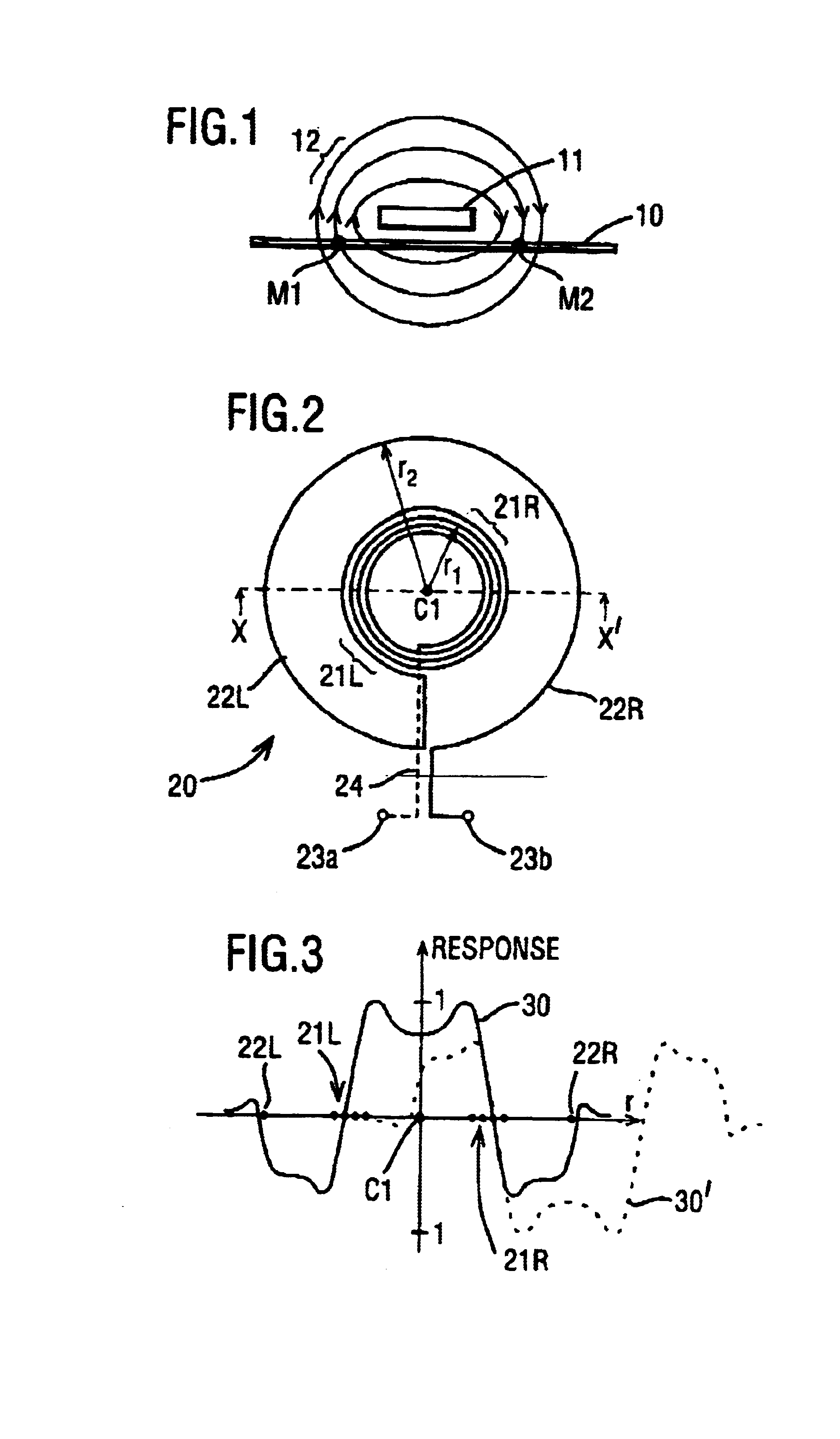
Referring to FIG. 1, there is shown a cross-sectional view of a printed circuit board (PCB) 10 and a load conductor 11. The load conductor 11 is mounted above the PCB with a small separation, for example in a range of 0.5 mm to 4 mm, between it and the PCB 10. If required, the load conductor 11 can alternatively be made integral with the PCB 10.

The load conductor 11 is shown with a current flowing through it into the plane of the drawing. This current produces magnetic field lines 12 which encircle, in a clockwise direction as illustrated by arrows on the magnetic field lines 12 in the drawing, the load conductor 11. To a left-hand-side of the load conductor 11, the magnetic field lines 12 rise out of the plane of the PCB 10 and are concentrated in a region whose effective magnetic centre is designated by M1. On a right-hand-side of the load conductor 11, the magnetic field lines 12 descend into the plane of the PCB 10 and are concentrated in a region whose effective magnetic centre...


PUM


Abstract

A current sensor for measuring the load in a fiscal power meter has conductive paths connected between an inlet and an outlet for guiding the load currents through the sensor, and operates by sensing local magnetic fields generated around the conductive paths by the current flowing there through, thereby providing a current measure indicative of the magnitude of a given load. The sensor is distinguished by plural current coil elements arranged in a substantially common plane so as to be substantially insensitive to remotely generated magnetic fields but responsive to local magnetic fields for generating the current measure. The coil elements are disposed in zones having more than two effective centres and exhibiting mutually opposing responses to the remote field.

Description

The present invention relates to current sensors for measuring current flowing in conductors. More particularly, but not exclusively, the invention relates to a current sensor forming part of an alternating current (AC) fiscal electricity meter for measuring the energy supplied by a utility company.BACKGROUND TO THE INVENTIONIn a published PCT patent application PCT / GB00 / 02851 (WO 01 / 11376), there is described a current sensor which responds to a magnetic field generated by a current flowing in a load conductor.In a published U.S. Pat. No. 4,894,610, there is described a current-transformer arrangement for a static electricity meter.In a published PCT patent application no. PCT / GB00 / 02604, there is described an electronic circuit formed on a printed circuit board which is configured as a current-to-voltage converter using a printed circuit track as a sensor, the sensor being placed in parallel with a primary current carrying conductor, for example a bus bar.Situations arise where a ...

Claims


Application Information

Patent Timeline
Patent Type & Authority Patents(United States)
IPC IPC(8): G01R15/14G01R15/18G01R22/00
CPCG01R15/18G01R15/185G01R22/00
Inventor COLBY, EDWARD GRELLIERSTORKEY, MATTHEW EMMANUEL MILTON
Owner COLBY EDWARD GRELLIER
Why Eureka
Try Eureka