Mechanism for switching airflow mode of air blower/vacuum

a technology of air blower/vacuum and airflow mode, which is applied in the direction of cleaning equipment, household applications, suction cleaners, etc., can solve the problems of increasing the cost of air blower/vacuum and not being suitable for compact air blower/vacuum use, and achieves the effect of reducing production costs and easy production

Inactive Publication Date: 2004-05-18
RYOBI
View PDF6 Cites 43 Cited by
  • Summary
  • Abstract
  • Description
  • Claims
  • Application Information

AI Technical Summary

Benefits of technology

It is an objective of the present invention to overcome the above-described problems and to provide a mechanism for switching airflow mode of an air blower / vacuum that enables easily switching the air blower / vacuum between a vacuum mode and a blower mode, that is suitable for a compact air blower / vacuum, and that enables configuring an air blower / vacuum with few components.
With this configuration, the air blower / vacuum can be switched between its vacuum mode and its blower mode by merely moving the nozzle with respect to the main body. Therefore, there is no need to provide a separate mode switching unit. For this reason, fewer components are required to produce the air blower / vacuum so that production costs can be decreased. Also, the air blower / vacuum can be easily produced in a compact shape.
With this configuration, the air blower / vacuum can be switched between its vacuum mode and its blower mode by merely rotating the nozzle around its central axis. Therefore, there is no need to provide a separate mode switching unit. For this reason, fewer components are required to produce the air blower / vacuum so that production costs can be decreased. Also, the air blower / vacuum can be easily produced in a compact shape.

Problems solved by technology

It is not suitable for use in compact air blower / vacuums, because the special switching unit would increase the size of the air blower / vacuum.
Also, it requires extra components and so would increase the cost of the air blower / vacuum.

Method used


Image

  • Mechanism for switching airflow mode of air blower/vacuum
  • Mechanism for switching airflow mode of air blower/vacuum
  • Mechanism for switching airflow mode of air blower/vacuum

Examples


Embodiment Construction

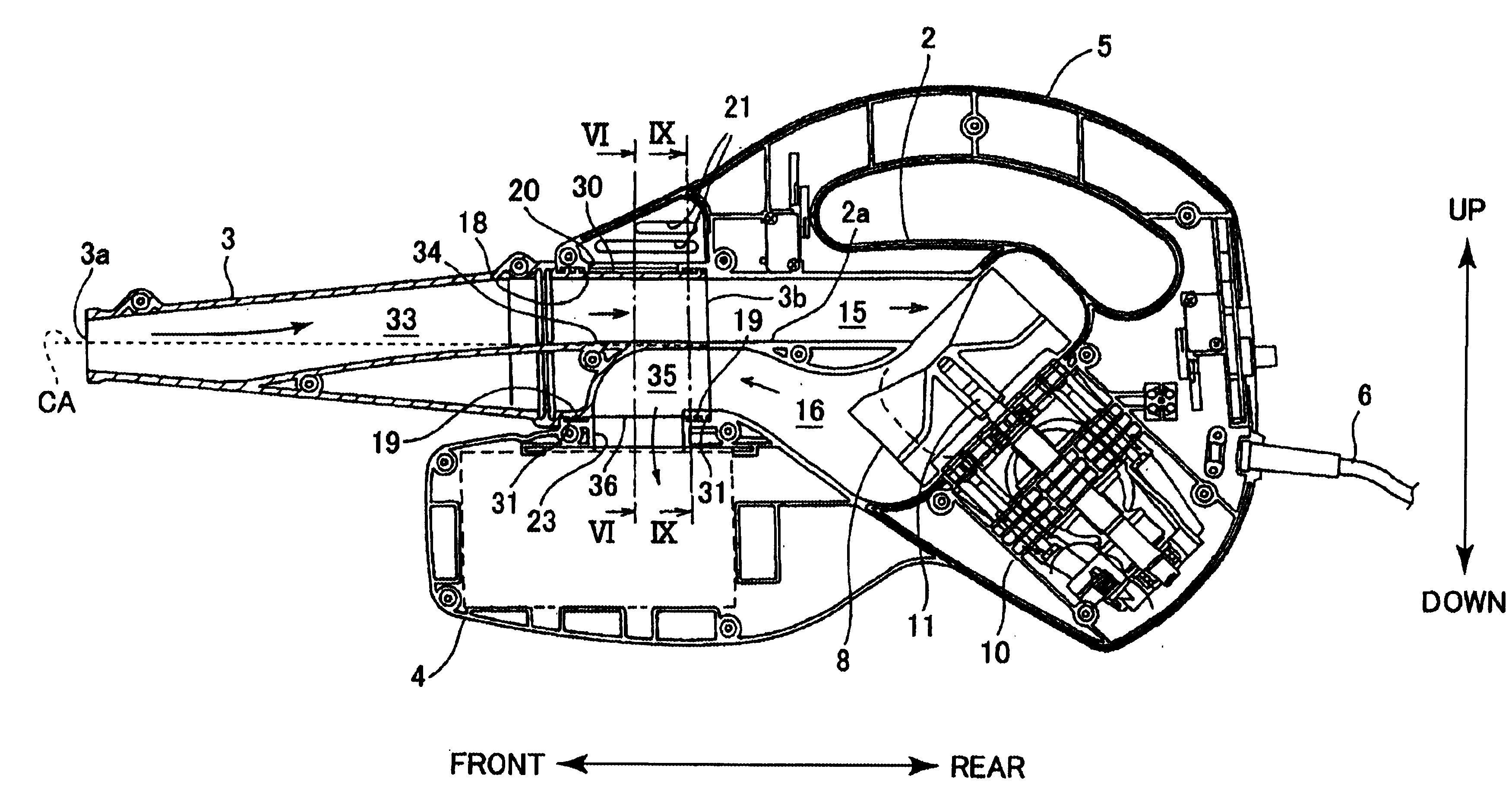
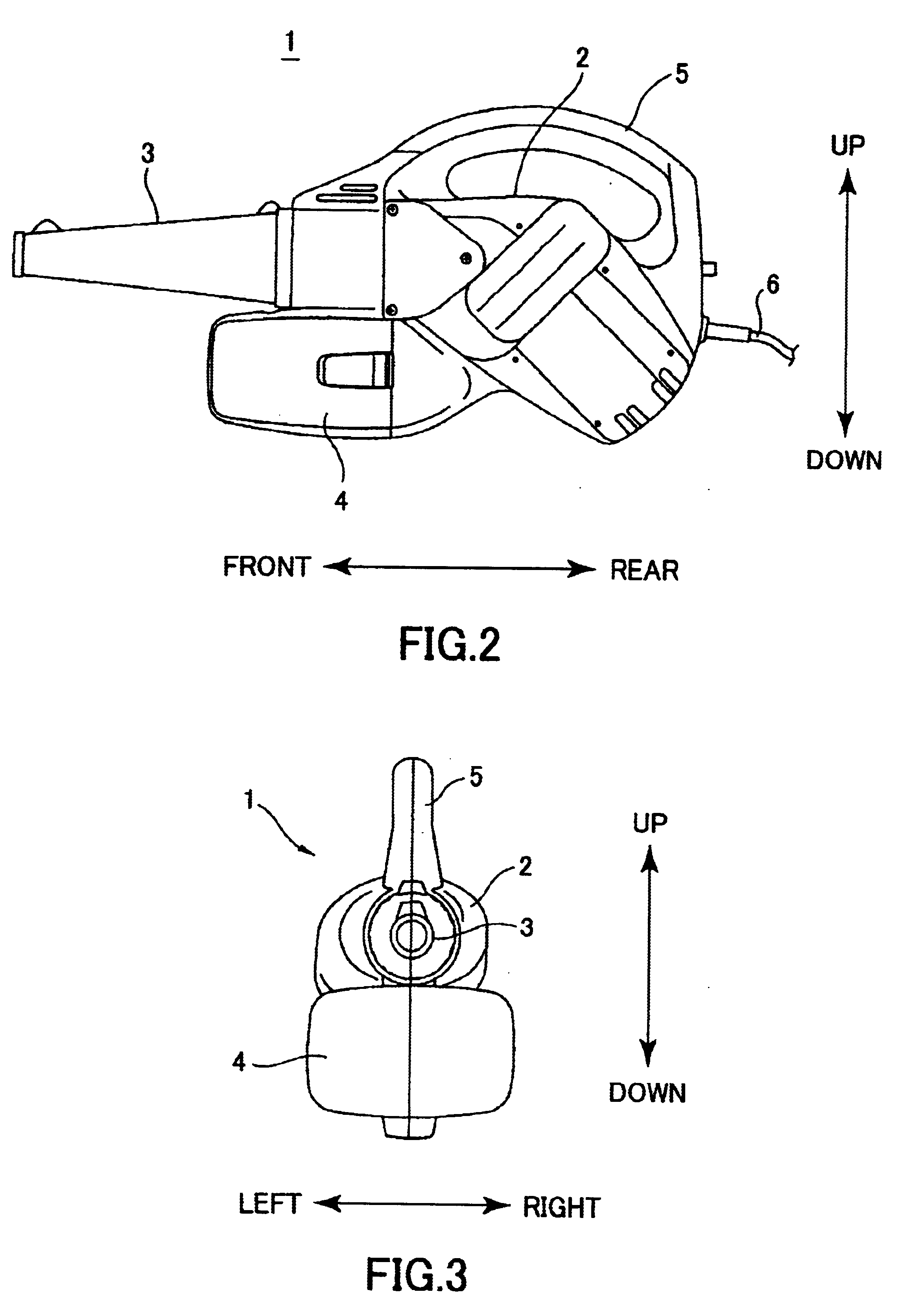
Next, an air blower / vacuum 1 according to an embodiment of the present invention will be described with reference to the attached drawings. Unless otherwise noted, orientational terms such as front, rear, up, down, left, and right, will refer to directions indicated in the drawings.

The air blower / vacuum 1 is capable of generating a suction force for gathering dust, trash, and the like, and an air jet for dispersing dust. As shown in FIGS. 1 and 2, the air blower / vacuum 1 includes a main body 2 and a nozzle 3. The nozzle 3 is attached to the front of the main body 2 and extends forward in a tapering shape. A dust container 4 is provided below the main body 2. The dust container 4 is for collecting dust that is sucked up by the air blower / vacuum 1. A handle 5 is formed to protrude upward in a slight arc shape at the upper portion of the main body 2. The handle 5 is used by the operator of the air blower / vacuum 1 to grasp and carry the air blower / vacuum 1 around. As shown in FIG. 4, an...


PUM


Abstract

An air blower / vacuum includes a nozzle, a fan, and a main body. The main body is formed with a vacuum pathway and a blower pathway, located upstream and downstream, respectively, from the fan with respect to the flow of air. The main body is also formed with an attachment hole in fluid communication with both the vacuum pathway and the blower pathway. The attachment hole supports the nozzle rotatable between a vacuum mode orientation and a blower mode orientation. In the vacuum mode orientation, the pathway of the nozzle is in fluid communication with the vacuum pathway. In the blower mode orientation, the pathway of the nozzle is in fluid communication with the blower pathway.

Description

1. Field of the InventionThe present invention relates to a mechanism for switching the airflow mode of an air blower / vacuum, which is used for gathering or dispersing dust and the like.2. Description of the Related ArtThere has been known an air blower / vacuum capable of generating a vacuum force for gathering dust, trash, and the like, and an air jet for dispersing dust.FIG. 1 is a schematic view showing an air blower / vacuum 50 described in International Publication WO97 / 30620. The air blower / vacuum 50 includes an electric motor 51, a fan 52, a vacuum nozzle 53, and a blower nozzle 54. The electric motor 51 drives the fan 52 to rotate and generate an airflow. The vacuum nozzle 53 serves as a vacuum pathway provided upstream, with respect to direction of the airflow, from the fan 52. The blower nozzle 54 serves as a blower pathway provided downstream, with respect to direction of the air flow, from the fan 52. The vacuum nozzle 53 and the blower nozzle 54 are disposed one on top of ...

Claims


Application Information

Patent Timeline
Patent Type & Authority Patents(United States)
IPC IPC(8): A47L5/14A47L5/12A47L5/28
CPCA47L5/14
Inventor OOHAMA, SHINJI
Owner RYOBI
Why Eureka
Try Eureka