Cover for a sealed linear encoder and a sealed linear encoder

a technology of encoder and encoder, which is applied in the direction of optical conversion of sensor output, instruments, measurement devices, etc., can solve the problems of cumbersome provision of angular cover formed by protecting sheet around the hollow body, affecting measurement precision, damage or destruction of sealed linear encoder

Inactive Publication Date: 2004-05-25
HEIDENHAIN CORP +1
View PDF8 Cites 26 Cited by
  • Summary
  • Abstract
  • Description
  • Claims
  • Application Information

AI Technical Summary

Benefits of technology

The present invention provides a cover for an effective protection of the sealed linear encoder from dust or spray water, from a danger and damage to the measurement system from chips or hot metal parts, and from an enduring and direct wetting by cooling and lubricating fluid. At the same time, the cover is simple to manufacture and to mount. The cover is suitable for newly installed sealed linear encoders as well as for supplementing existing sealed linear encoders without requiring constructive changes to the objects moved relative to one another or to the sealed linear encoders. Furthermore, the cover according to the present invention is suitable for different ways of attaching the sealed linear encoders to the objects moved relative to one another without requiring time consuming changes to the cover or different types of covers.
For an easy mounting of the cover to the hollow body of the sealed linear encoder, the cover includes leg profiles at the inner sides facing the hollow body, which leg profiles correspond to profiles at the top side and the side wall of the hollow body opposite the mounting wall, so as to provide a compression, plug or snap connection between the cover and the hollow body.
The indent can serve as an additional seal with respect of the mounting wall as well as to adapt the cover to different widths or shapes of the measurement system or the mounting rail connected to the measurement system.
Accordingly, that portion of the leg of the L-shaped cover abutting the top side of the hollow body which extends in between the indent and the mounting wall may be pivotable about the indent, and an end portion thereof may sealingly abut the mounting wall or the mounting rail connected to the mounting wall of one of the two objects, or the indent may form a predetermined breaking point in order to shorten that leg of the L-shaped cover which abuts the top side of the hollow body.

Problems solved by technology

This can affect the measurement precision and damage or destroy the sealed linear encoder.
However, the provision of an angular cover formed by a protecting sheet extending around the hollow body is cumbersome since the protecting sheet needs to be screwed to the mounting wall of one of the two objects moved relative to the other, or to be clamped in between a mounting rail for receiving the hollow body and the mounting wall.

Method used


Image

  • Cover for a sealed linear encoder and a sealed linear encoder
  • Cover for a sealed linear encoder and a sealed linear encoder
  • Cover for a sealed linear encoder and a sealed linear encoder

Examples


Embodiment Construction

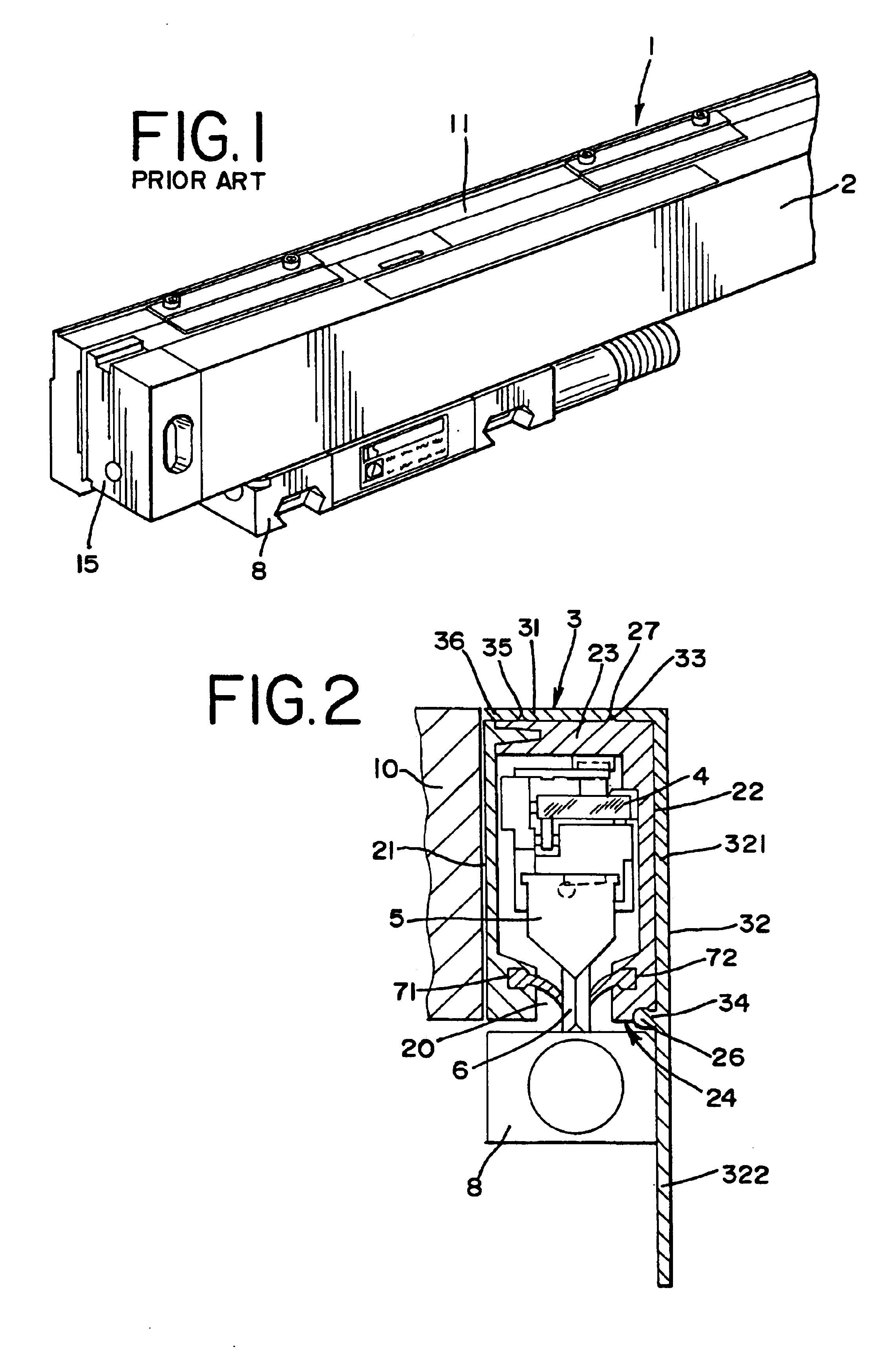
FIG. 1 illustrates a perspective view of a known-sealed linear encoder 1. The encoder 1 is connected to a mounting rail 11 attached to the mounting wall of one of two objects moved relative to one another, such as a machine-tool base. The sealed linear encoder 1 includes a scale unit arranged within a hollow body 2 whose front ends are formed by end portions 15. At the bottom side of the hollow body 2, a mounting block 8 is arranged which is connected to the other of the two objects moved relative to one another, such as the tool carrier of a machine-tool.

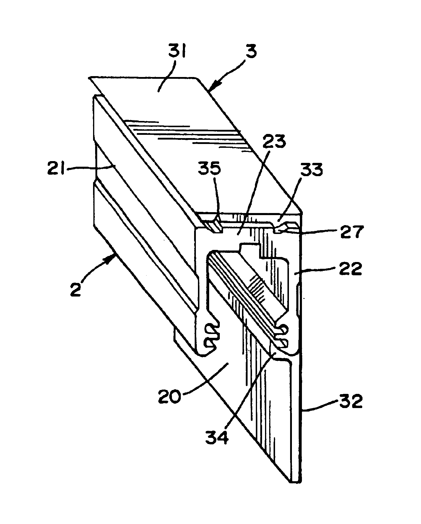
FIG. 2 shows a section through a sealed linear encoder according to FIG. 1. FIG. 2 illustrates that a scale unit 4 is arranged inside the hollow body 2. A scanning trolley forming a scanning unit 5 is guided along the scale unit 4 in a measurement direction for scanning the scale unit 4. The scanning trolley is connected with the mounting block 8 arranged at the bottom side 24 of the hollow body 2 via a carrier 6 extending through ...


PUM


Abstract

A sealed linear encoder for determining the relative position of a first object and a second object. The sealed linear encoder includes a scale unit arranged in a hollow body that is mounted to a mounting structure associated with the first object and includes a slot which extends in a direction of measurement. A scanning unit for scanning the scale unit and a carrier connected to the second object, wherein the carrier extends through the slot. Sealing lips arranged at the hollow body and abutting the carrier so as to seal the carrier and a cover form-fitted to the hollow body for covering at least the slot.

Description

1. Field of the InventionThe present invention relates to a sealed linear encoder for determining the position of two objects relative to one another and a cover for a sealed linear encoder.2. Discussion of Related ArtSealed linear encoders of this type include a hollow body connected to one of the two objects. The hollow body contains a scale unit with a scale, and a scanning unit for scanning the scale unit. The scanning unit is connected to a mounting block outside the hollow body via a carrier, and the mounting block is connected to the second object. The carrier extends through a slot in the hollow body from the inside to the mounting block outside of the hollow body. The slot extends in the direction of measurement. When the two objects move relative to one another, the movement of one of the objects is transmitted to the graduation of the scale unit wherein the carrier is moved in the direction of measurement and the movement of the carrier is measured.In order to protect the...

Claims


Application Information

Patent Timeline
Patent Type & Authority Patents(United States)
IPC IPC(8): G01D5/26G01D5/347
CPCG01D5/34769
Inventor MULLER, JOSEF
Owner HEIDENHAIN CORP
Why Eureka
Try Eureka