Cover for a sealed linear encoder and a sealed linear encoder

a technology of encoder and encoder, which is applied in the field of cover for a sealed linear encoder, can solve the problems of cumbersome provision of an angular cover formed by a protecting sheet around the hollow body, affecting measurement precision, damage or destruction of the sealed linear encoder,

Inactive Publication Date: 2003-10-30
HEIDENHAIN CORP +1
View PDF2 Cites 17 Cited by
  • Summary
  • Abstract
  • Description
  • Claims
  • Application Information

AI Technical Summary

Problems solved by technology

This can affect the measurement precision and damage or destroy the sealed linear encoder.
However, the provision of an angular cover formed by a protecting sheet extending around the hollow body is cumbersome since the protecting sheet needs to be screwed to the mounting wall of one of the two objects moved relative to the other, or to be clamped in between a mounting rail for receiving the hollow body and the mounting wall.

Method used


Image

  • Cover for a sealed linear encoder and a sealed linear encoder
  • Cover for a sealed linear encoder and a sealed linear encoder
  • Cover for a sealed linear encoder and a sealed linear encoder

Examples


Embodiment Construction

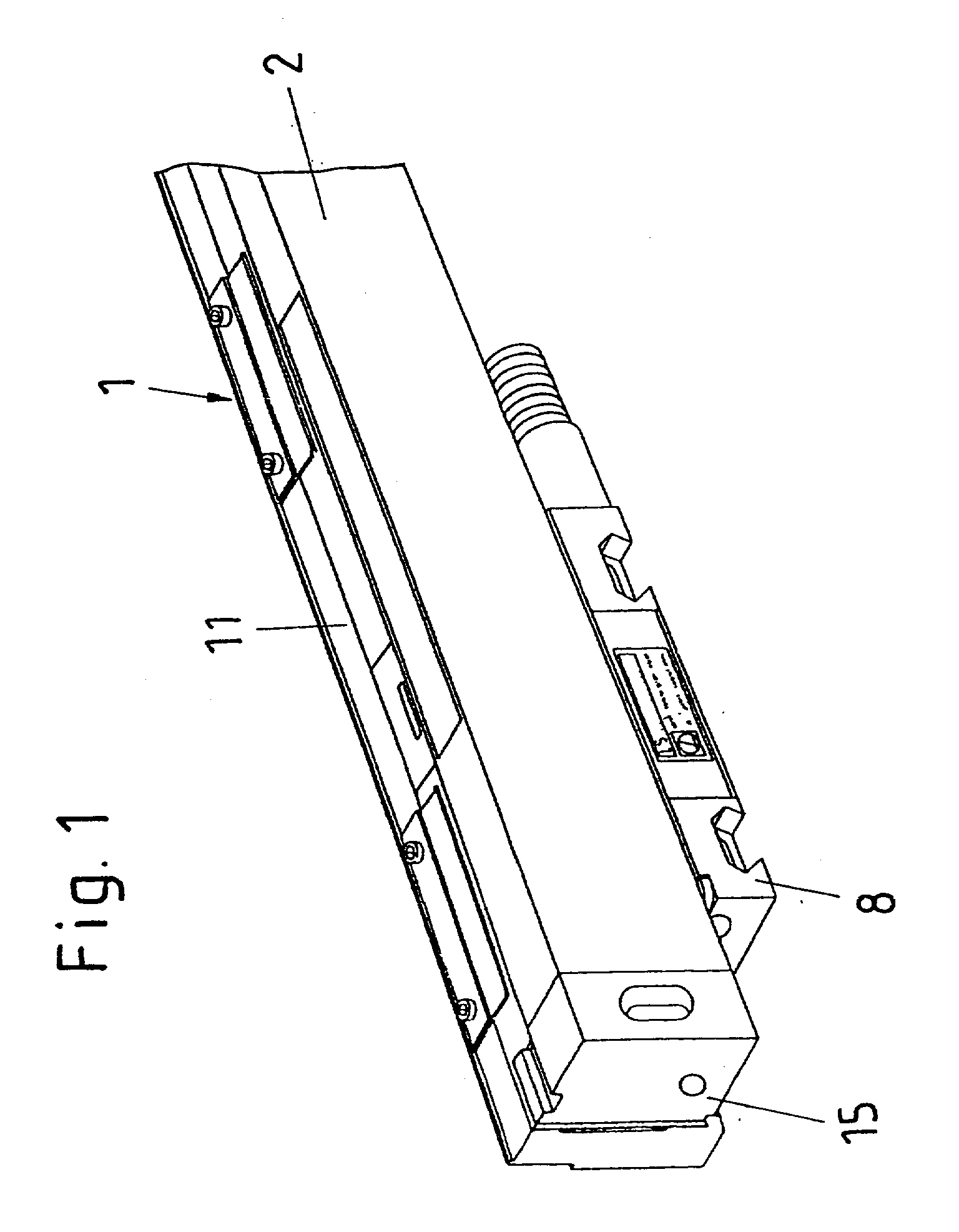
[0032] FIG. 1 illustrates a perspective view of a sealed linear encoder 1. The encoder 1 is connected to a mounting rail 11 attached to the mounting wall of one of two objects moved relative to one another, such as a machine-tool base. The sealed linear encoder 1 includes a scale unit arranged within a hollow body 2 whose front ends are formed by end portions 15. At the bottom side of the hollow body 2, a mounting block 8 is arranged which is connected to the other of the two objects moved relative to one another, such as the tool carrier of a machine-tool.

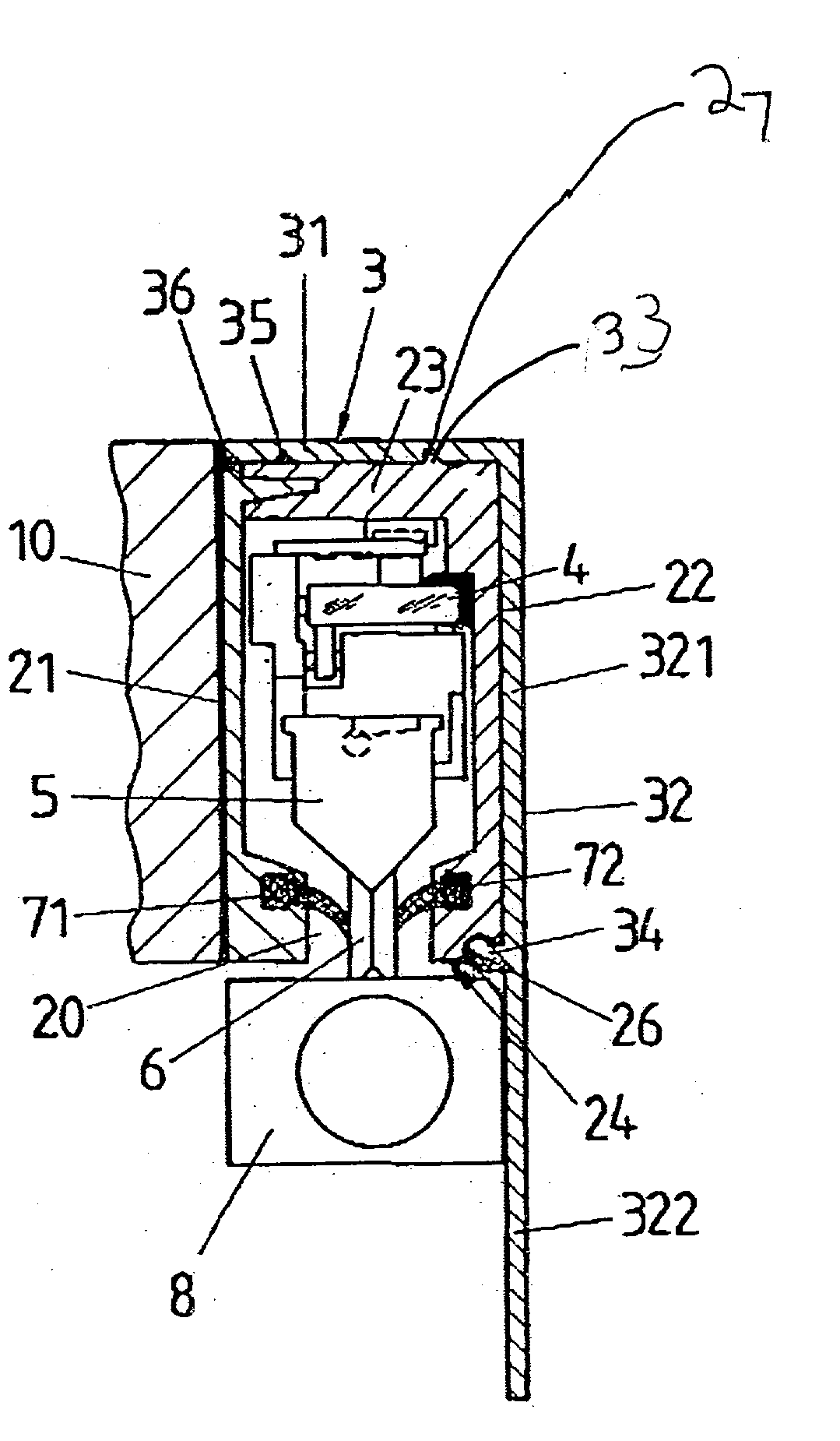
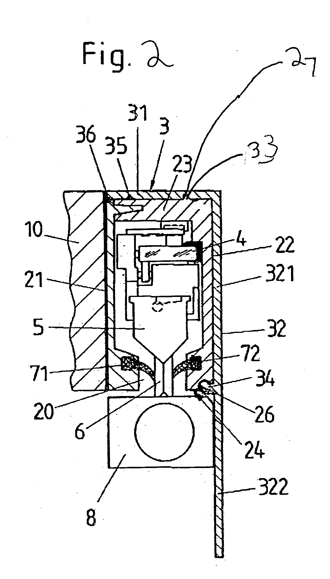
[0033] FIG. 2 shows a section through a sealed linear encoder according to FIG. 1. FIG. 2 illustrates that a scale unit 4 is arranged inside the hollow body 2. A scanning trolley forming a scanning unit 5 is guided along the scale unit 4 in a measurement direction for scanning the scale unit 4. The scanning trolley is connected with the mounting block 8 arranged at the bottom side 24 of the hollow body 2 via a carrier 6 extending ...


PUM


Abstract

A sealed linear encoder for determining the relative position of a first object and a second object. The sealed linear encoder includes a scale unit arranged in a hollow body that is mounted to a mounting structure associated with the first object and includes a slot which extends in a direction of measurement. A scanning unit for scanning the scale unit and a carrier connected to the second object, wherein the carrier extends through the slot. Sealing lips arranged at the hollow body and abutting the carrier so as to seal the carrier and a cover form-fitted to the hollow body for covering at least the slot.

Description

[0001] 1. Field of the Invention[0002] The present invention relates to a sealed linear encoder for determining the position of two objects relative to one another and a cover for a sealed linear encoder.[0003] 2. Discussion of Related Art[0004] Sealed linear encoders of this type include a hollow body connected to one of the two objects. The hollow body contains a scale unit with a scale, and a scanning unit for scanning the scale unit. The scanning unit is connected to a mounting block outside the hollow body via a carrier, and the mounting block is connected to the second object. The carrier extends through a slot in the hollow body from the inside to the mounting block outside of the hollow body. The slot extends in the direction of measurement. When the two objects move relative to one another, the movement of one of the objects is transmitted to the graduation of the scale unit wherein the carrier is moved in the direction of measurement and the movement of the carrier is meas...

Claims


Application Information

Patent Timeline
Patent Type & Authority Applications(United States)
IPC IPC(8): G01D5/347
CPCG01D5/34769
Inventor MULLER, JOSEF
Owner HEIDENHAIN CORP
Why Eureka
Try Eureka