Mobile partitioning wall

Active Publication Date: 2011-10-11
DORMAKABA DEUT GMBH
View PDF79 Cites 39 Cited by
  • Summary
  • Abstract
  • Description
  • Claims
  • Application Information

AI Technical Summary

Benefits of technology

[0041]The overall partitioning wall fulfils the requirements of the thermal insulation regulation suc

Problems solved by technology

As, substantially, the structural units are not located at the en

Method used


Image

  • Mobile partitioning wall
  • Mobile partitioning wall
  • Mobile partitioning wall

Examples


Embodiment Construction

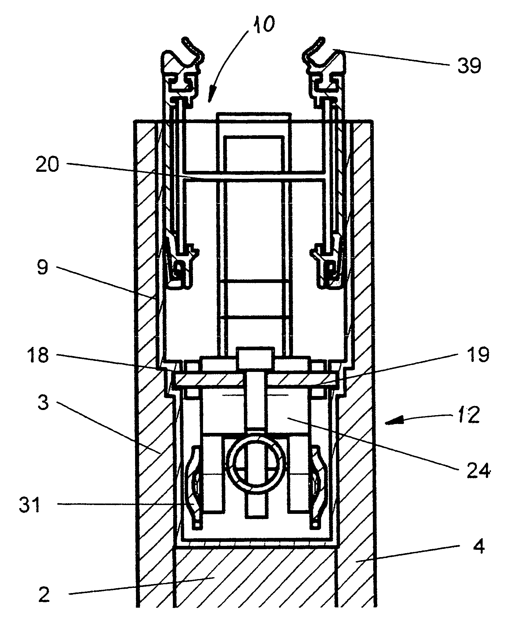
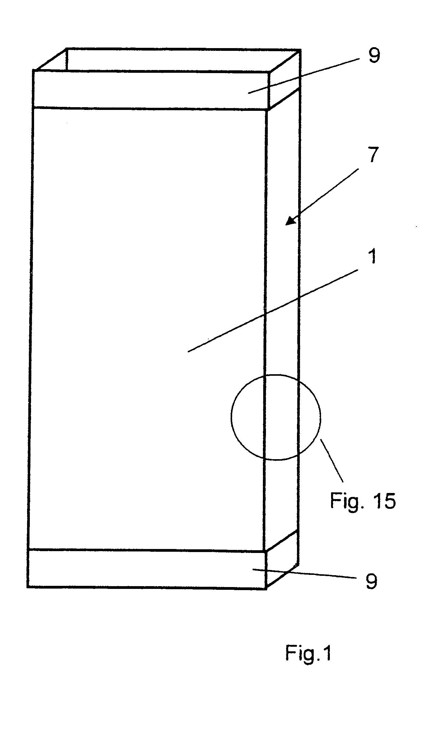
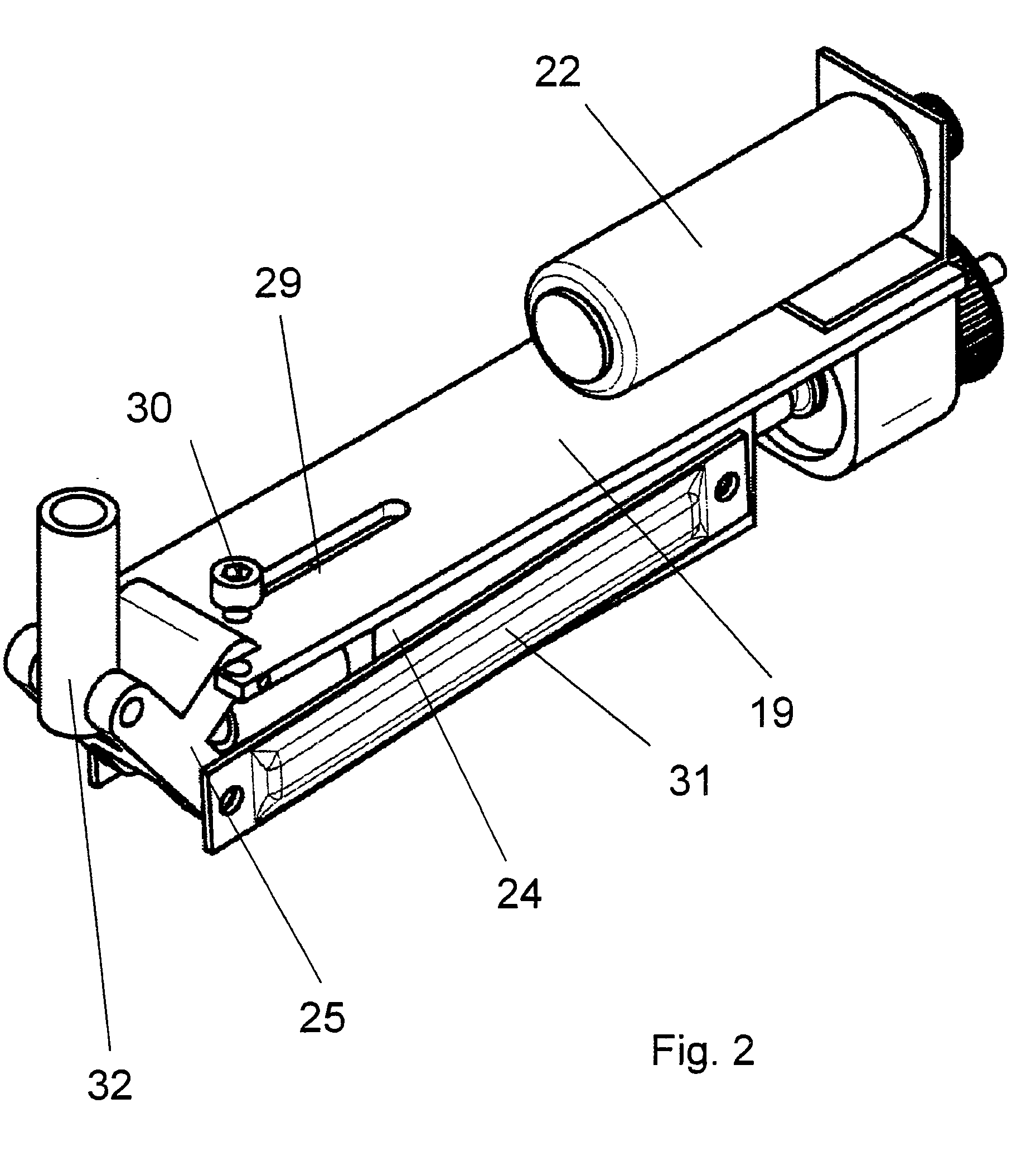
[0059]A mobile partitioning wall is composed of several panel-like, independently displaceable, suspendedly supported wall elements 1 and is suitable as a room divider or as an outside termination. Depending on the execution, the individual wall elements 1 may be displaced manually or driven by motor. All wall elements 1 can be moved out of a space-saving parking position, a so-called stacking location, and into the axis of the partitioning wall and be secured there.

[0060]For the sake of clarity, in all Figures a wall element 1 is diagrammatically and partially illustrated, in order to be able to describe the corresponding structure in a correspondingly detailed form.

[0061]In the following Figures described below, wall elements 1 are illustrated having respectively one mounting element 9 disposed at each horizontal edge. The mounting element 9 includes respectively one sealing mechanism 10 realizing a functional termination of rooms or buildings with regard to an acceptable thermal,...


PUM


Abstract

Mobile partitioning wall with several wall elements displaceably suspended in running rails. The mobile partitioning wall have structural units that are technically simple to manufacture and to mount and are structured to be universally usable and can be easily and variably disposed at the edge sides of individual wall elements. The wall elements have mounting elements that are horizontally and/or vertically disposed at the edge sides. Modular structural units are laterally insertable into the mounting elements.

Description

CROSS-REFERENCE TO RELATED APPLICATIONS[0001]This is a U.S. national stage of International Application No. PCT / EP2006 / 008855, filed on 12 Sep. 2006. Priority is claimed on German Application No. 10 2005 048 157.4, filed on 6 Oct. 2005.BACKGROUND OF THE INVENTION[0002]1. Field of the Invention[0003]The invention is based on a mobile partitioning wall having wall elements which are displaceably disposed at a running rail.[0004]2. Description of the Related Art[0005]A mobile partitioning wall with several wall elements, which are displaceably guided in a running rail, is known from DE-OS 24 04 874. Each wall element has a supporting structure, which is formed by a surrounding frame consisting of profiles. Covering panels are mounted to both sides of the frame and, moreover, additional add-on and accessory parts are attached thereto. The hollow space between the covering panels and the frame is filled with thermally insulating and sound-absorbent materials.[0006]The frame-based support...

Claims


Application Information

Patent Timeline
IPC IPC(8): E04H14/00
CPCE04B2/827
Inventor LUTTMANN, OLAFHOOPMANN, HARALD
Owner DORMAKABA DEUT GMBH
Why Eureka
Try Eureka