Lightning receptor for a wind turbine rotor blade

a technology of lightening receptor and wind turbine, which is applied in the direction of motors, wind energy generation, climate sustainability, etc., can solve the problems of irreparable damage to the rotor blade repeatedly and again, and the wind turbine is particularly affected, so as to prevent the damage to the rotor blade during lightning strikes, the effect of simple manufacture and mounting

Active Publication Date: 2019-12-31
NORDEX ENERGY SE & CO KG
View PDF16 Cites 0 Cited by
  • Summary
  • Abstract
  • Description
  • Claims
  • Application Information

AI Technical Summary

Benefits of technology

[0013]It is an object of the invention to provide a lightning receptor for a wind turbine rotor blade that effectively prevents damage to the rotor blade during lightning strikes and is simple to manufacture and to mount and, where appropriate, to replace.
[0018]Such damage is counteracted in the case of the invention by virtue of the fact that a receptor-nose-edge-side leg and a receptor-end-edge-side leg shield the fastening portion of the lightning receptor that is arranged in the interior of the rotor blade. The striking of positive lightning flashes into the fastening portion is avoided since, even with the receptor tip shielded by the space-charge effect explained, a lightning strike into the receptor nose edge or receptor end edge is more probable.
[0019]A further advantage of a lightning receptor according to the invention is the simple and secure fastening to the wind turbine rotor blade with the aid of the two mutually opposite adhesive bonding surfaces. These are formed by recesses in the receptor pressure side and the receptor suction side. Engaging in these recesses are complementarily formed fastening portions of the wind turbine rotor blade which, where appropriate only upon mounting of the lightning receptor, are formed in a laminating process by a fiber-reinforced plastic material. In this way, a secure hold is achieved by adhesive bonding surfaces the formation of which does not require any particular lightning-strike-endangered edges in the surroundings of the adhesive bonding surfaces. Should at some point a replacement of the lightning receptor be required, the laminate portions can be simply removed and built on anew.
[0022]In one embodiment, the recesses are rectangular or trapezoidal. This statement relates in particular to a view in the direction of the receptor pressure side or the receptor suction side. In particular, a trapezoidal configuration of the recesses allows secure fastening, with more or less uniformly wide portions of the receptor pressure side and receptor suction side remaining in the longitudinal direction of the lightning receptor. Independently thereof, the recesses can also be rectangular or trapezoidal in cross section.
[0026]In one embodiment, the connection means are arranged on an end face of the fastening portion that is arranged closer to the receptor tip than an end of the fastening portion that is remote from the receptor tip. The end face can be oriented substantially perpendicularly to the receptor suction side and pressure side. In the stated arrangement of the connection means, particularly effective shielding also of the connection region of the lightning conductor is achieved by the receptor-end-edge-side and receptor-nose-edge-side legs of the receptor tip. Consequently, it is possible to fasten the lightning conductor to the receptor tip via a force-locking connection (screw connection). In the case of conventional receptor tips, the lightning conductor is connected to the receptor tip by an integrally bonded connection, since the tip can be produced free of edges. A screw connection is more advantageous in view of repairs on the lightning protection system. However, this type of connection is much more attractive for lightning flashes on account of the edges present and would have to be enclosed by a corresponding isolation layer. In accordance with the present invention, the use of a screw connection is possible without problems since the connection point is shielded from lightning strikes by the receptor-end-edge-side leg and receptor-nose-edge-side leg of the receptor tip.
[0027]In one embodiment, the end face has a concave curvature. By virtue of this measure, the connection region for the lightning conductor is particularly effectively integrated into the shielded region of the fastening portion. Particularly if a relatively large radius of curvature is chosen, for example in the range from 5 cm to 20 cm, the formation of edges attractive for a lightning strike is avoided.

Problems solved by technology

Owing to their large overall height, wind turbines are affected particularly frequently by a lightning strike.
In practice, however, damage occurs again and again to the rotor blades through lightning strikes.
Here, for example, fiber-reinforced plastic materials of the rotor blade can be affected, leading to irreparable damage to the rotor blade.

Method used


Image

  • Lightning receptor for a wind turbine rotor blade

Examples


Embodiment Construction

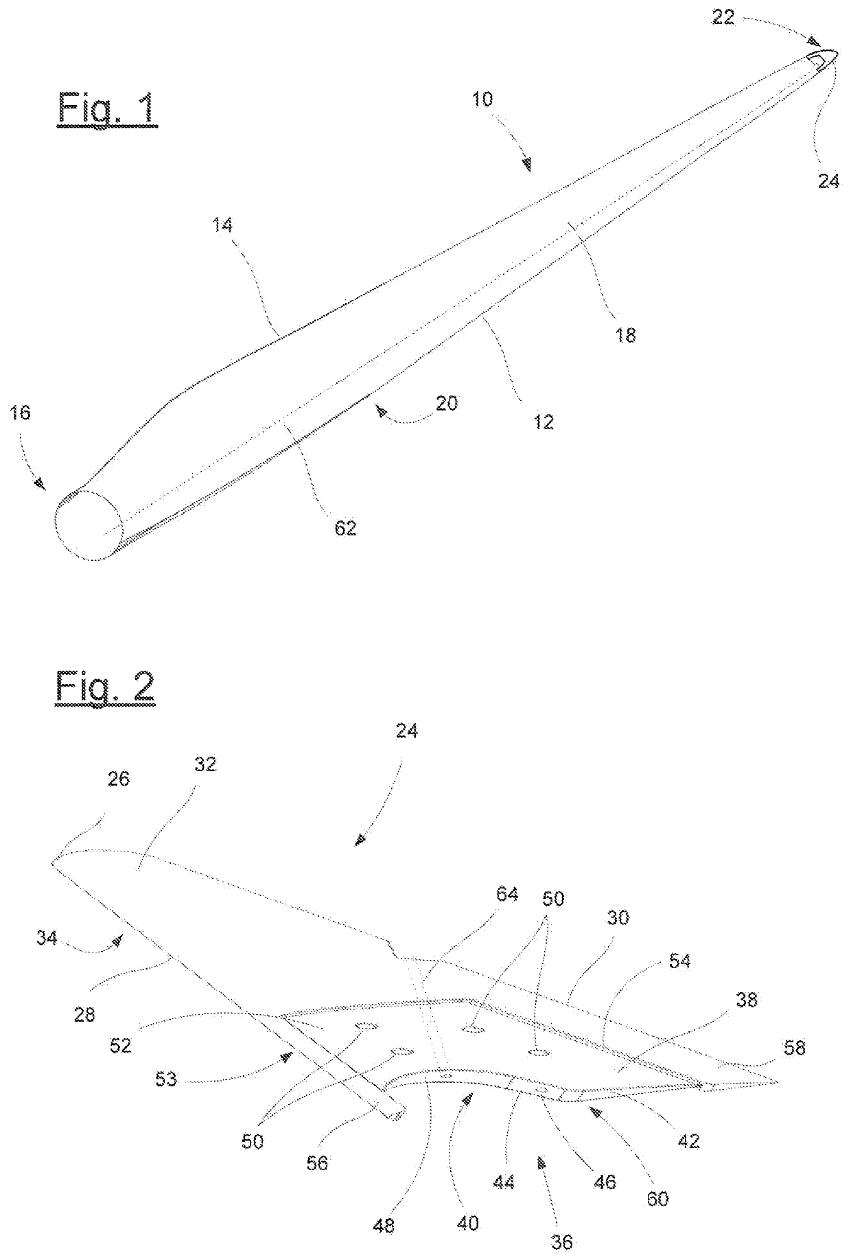
[0032]The wind turbine rotor blade 10 of FIG. 1 has a profile nose edge 12, a profile end edge 14, a blade root 16, a suction side 18 and a pressure side 20. The blade tip 22 is formed by a lightning receptor 24 to which there is connected a lightning conductor 62 extending in the interior of the wind turbine rotor blade 10 as far as the blade root 16.

[0033]Details of the lightning receptor 24 can be seen more clearly in FIG. 2. The lightning receptor 24 shown there is produced in one part in a casting process, in the example from aluminum. It has a receptor tip 26, a receptor nose edge 28, a receptor end edge 30, a receptor suction side 32 and a receptor pressure side 34, which faces away from the observer in FIG. 2. It can be seen that the lightning receptor 24 has an aerodynamic profile in cross section.

[0034]At the end facing the observer and remote from the receptor tip 26, the lightning receptor 24 has a fastening portion 36 which has two mutually opposite adhesive bonding sur...


PUM


Abstract

Lightning receptor for a wind turbine rotor blade, the lightning receptor being produced in one part in a casting process and having a receptor tip, a receptor suction side, a receptor pressure side, a receptor nose edge and a receptor end edge, defined by a fastening portion with two mutually opposite adhesive bonding surfaces which are formed by recesses in the receptor pressure side and in the receptor suction side, a receptor-nose-edge-side leg and a receptor-end-edge-side leg projecting beyond the fastening portion in a direction away from the receptor tip.

Description

CROSS REFERENCE TO RELATED APPLICATION[0001]This application claims priority of European patent application No. 16 170 064.6, filed May 18, 2016, the entire content of which is incorporated herein by reference.FIELD OF THE INVENTION[0002]The invention relates to a lightning receptor for a wind turbine rotor blade, wherein the lightning receptor is produced in one part in a casting process.BACKGROUND OF THE INVENTION[0003]Owing to their large overall height, wind turbines are affected particularly frequently by a lightning strike. Most frequently, the lightning strikes in the region of the tip of a rotor blade pointing straight up. In order to prevent damage to or even destruction of the rotor blade by the lightning strike, it is known to arrange a lightning receptor in the region of the rotor blade tip and to connect it to a lightning conductor. The current from a lightning flash striking the lightning receptor is then discharged via the lightning conductor to the rotor blade root, ...

Claims


Application Information

Patent Timeline
Patent Type & Authority Patents(United States)
IPC IPC(8): F03D80/30
CPCF03D80/30F03D1/0675F05B2230/21Y02E10/72Y02P70/50
Inventor OHLERICH, NICKKREMER, JOCHEN
Owner NORDEX ENERGY SE & CO KG
Why Eureka
Try Eureka