High aspect stereoscopic mode camera and method

a stereoscopic mode and camera technology, applied in the field of cameras, can solve the problems of only generating minimal three-dimensional information for images, "low aspect" stereo image pairs, and complexity

Inactive Publication Date: 2004-06-08
THE BF GOODRICH CO
View PDF15 Cites 176 Cited by
  • Summary
  • Abstract
  • Description
  • Claims
  • Application Information

AI Technical Summary

Problems solved by technology

The stereoscopic imagery generated by the above methods suffers from a disadvantage, in that the baseline between adjacent stereo images and the associated stereo angle .phi..sub.s, are typically relatively small, resulting in "low aspect" stereo image pairs.
Consequently, the imagery is only capable of generating minimal three-dimensional information.
Another disadvantage of the prior art is that in order to capture a stereo image of all points in the scene, three images must be taken of that scene and combined when using the typical 50-56% overlap.
Furthermore, the drawings and the complexity of the associated circuitry used by Hiramatsu suggest the use of line scan cameras.
The complexity is created by the need for the location and registration of scanned lines of imagery.

Method used


Image

  • High aspect stereoscopic mode camera and method
  • High aspect stereoscopic mode camera and method
  • High aspect stereoscopic mode camera and method

Examples


Embodiment Construction

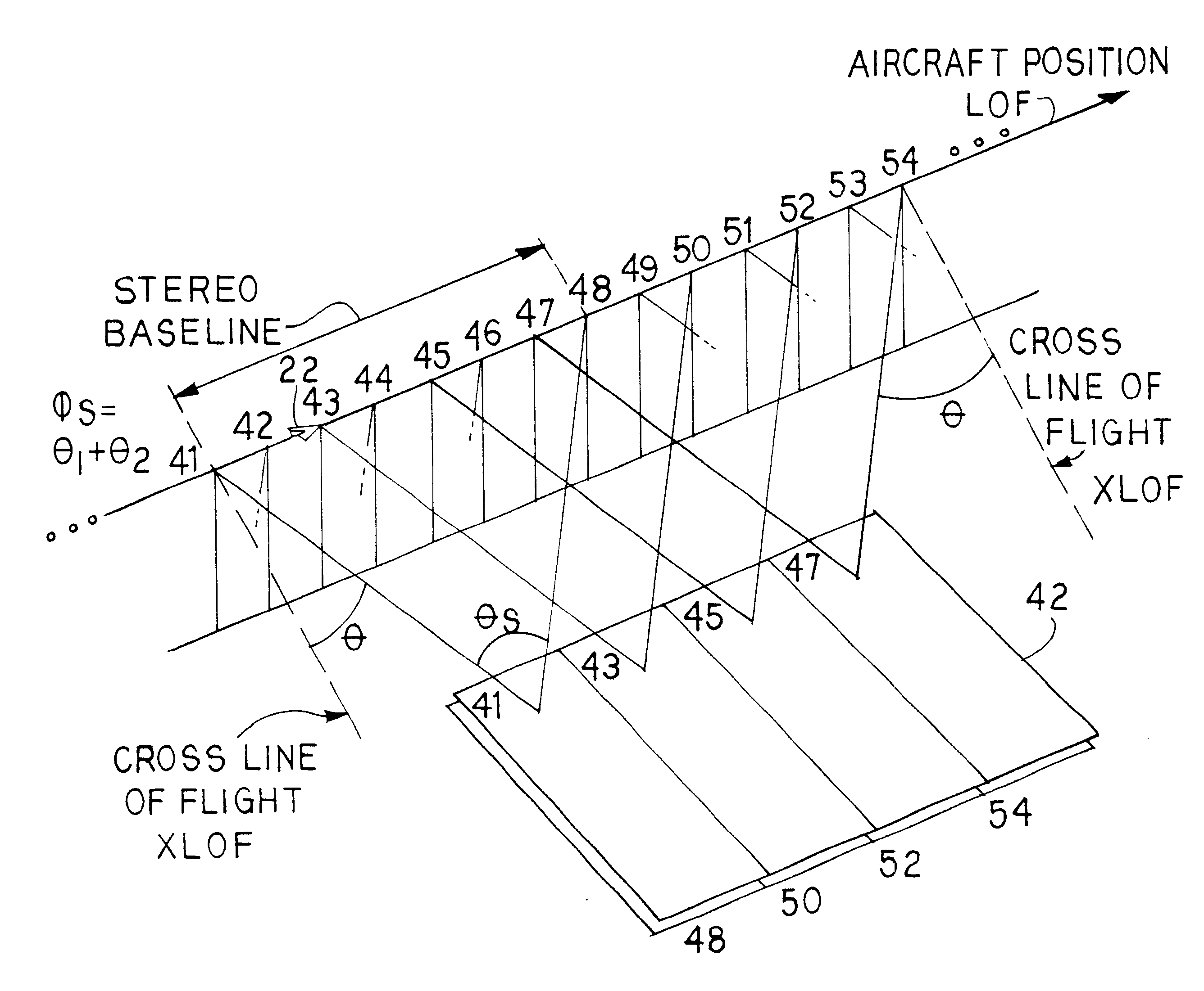
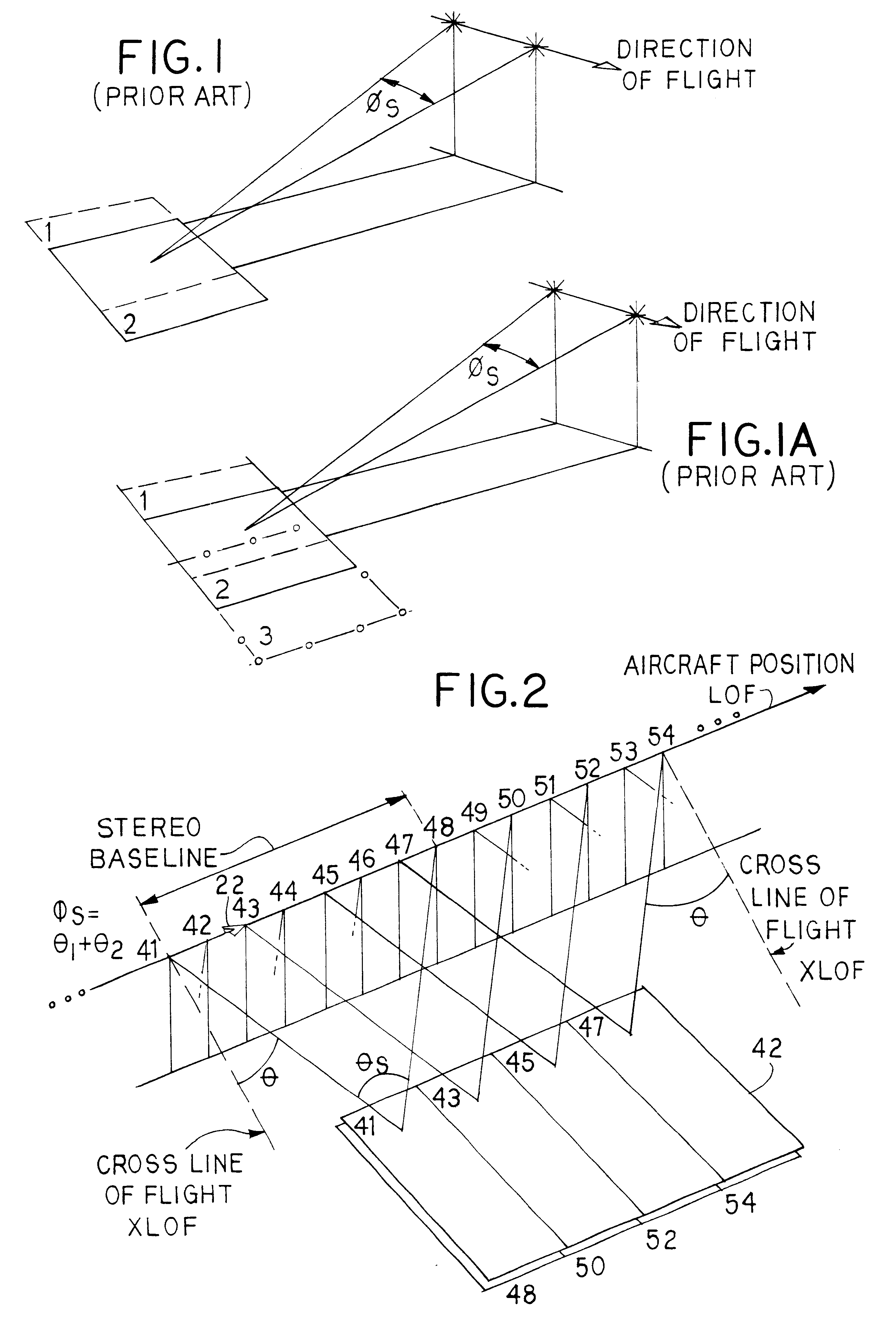
In a first aspect, and with reference to FIG. 2, a method is provided for operating a camera installed in a moving vehicle in a manner to generate high aspect stereo images. The primary application is in aerial photography, therefore the present discussion will be directed to that application. The invention is also applicable to any vehicle that is used to generate stereo imagery, including aircraft, terrestrial vehicles, and surface or submarine water craft.

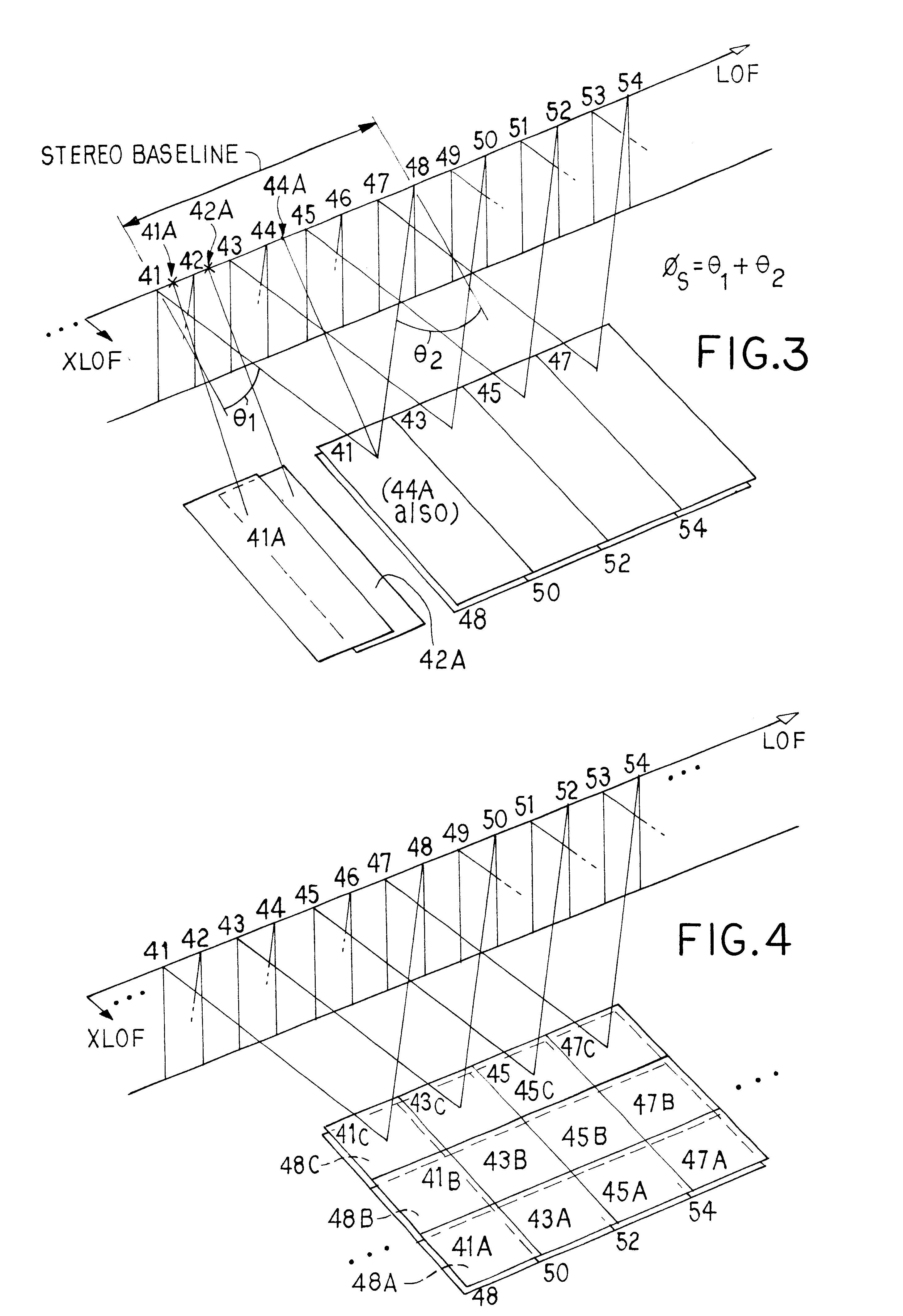
When the images are generated in a side oblique orientation (a typical scenario in aerial reconnaissance, surveillance and mapping), the method involves repeatedly rotating the camera about an azimuthal axis to generate images at two different azimuthal angles (.theta.1 and .theta.2), which will be preferably, but not necessarily, forward and aft of the cross line of flight direction. In the example of FIG. 2, the numbers 41, 42, 43, 44 . . . indicate the sequence of images generated by the camera and the position of the aircraf...


PUM


Abstract

An aerial reconnaissance camera and method provides for generating a first image of the terrain of interest with the camera pointing angle oriented or rotated about an azimuthal axis some angular amount (theta1) to a first, typically forward orientation, i.e., forward of a cross-line of flight direction. An image is obtained of the ground at this orientation. Then the camera is rotated about the azimuthal axis to new angular value (theta2), which will typically be aft of the cross line of flight direction. An image is generated at this value. The camera is then rotated back to the value of theta1, and a second image in the forward orientation is generated. The camera is then rotated again to the value of theta2 and another image in the aft orientation is generated. This process of rotating the camera about the azimuthal axis and generating images in forward and aft orientations continues over and over. Eventually, as the aircraft flies past the terrain of interest, any given location in the terrain of interest will have been imaged from two different perspectives-forward and aft. The motion of the aircraft during the interim in combination with the values of theta1 and theta2 provide the high baseline for the stereo image pairs. By selection of suitable values for the angular separation of theta1 and theta2 (such as theta1=+10 degrees and theta2=-10 degrees) the result will be pairs of images of the terrain of interest having a large baseline, producing truly high aspect stereo images from a single camera. The method also works in a similar fashion by rotation back and forth about the pitch axis and imaging the terrain in forward oblique and aft oblique orientations.

Description

A. Field of the InventionThis invention relates generally to the field of cameras used for aerial reconnaissance, aerial surveying, mapping and other applications in which the camera is placed onboard a moving vehicle. The invention also relates to a method of operating such a camera so as to obtain high aspect stereo imagery of the earth in a manner such that an increased amount of three-dimensional information can be obtained of the terrain of interest as compared to prior methods. The invention is particularly well suited to both framing camera and line scanning cameras, and cameras based on either film or electro-optical image recording media.B. Description of Related ArtThe traditional method for collection of stereo imagery using a reconnaissance camera provides for the capture of images in successive scan cycles with at least 50% forward overlap (56% is a typical value). Two pictures are taken of each point on the ground from two successive camera positions along the flight p...

Claims


Application Information

Patent Timeline
Patent Type & Authority Patents(United States)
IPC IPC(8): G03B35/00H04N13/00H04N15/00
CPCG03B35/00H04N13/0221H04N13/0296H04N13/221H04N13/296
Inventor BENNETT, RUSSELL A.
Owner THE BF GOODRICH CO
Why Eureka
Try Eureka