Multi-reflecting ion optical device

a technology of optical devices and ion beams, applied in the direction of separation of dispersed particles, mass spectrometers, separation processes, etc., can solve the problems of loss of sensitivity, system lack of means to prevent beam divergence in the drift direction, and further increase of ion flight tim

Inactive Publication Date: 2012-08-07
SHIMADZU CORP
View PDF13 Cites 29 Cited by
  • Summary
  • Abstract
  • Description
  • Claims
  • Application Information

AI Technical Summary

Benefits of technology

[0009]The inventors have realised that the acceptance of a multi-reflecting ion optical device, such as a multi-reflecting TOF mass analyser, can be substantially increased if the conflicting tasks of ion beam lateral stability and longitudinal energy focusing are treated separately by creating independent distributions of electrostatic potential. This provides a significant improvement of existing multi-reflecting TOF analysers. The ion optical device of the invention can be also used (and have a number of unique advantages) as an ion trap with image current detection involving processing using a Fourier transform in order to obtain mass spectra, as an ion trap with mass-selective ejection (using several methods) of ions towards an ion detector or simply as a storage device for ions.

Problems solved by technology

Unfortunately, this system lacks any means to prevent beam divergence in the drift direction.
Due to an initial angular spread, the width of the beam may exceed the width of the detector making further increase of ion flight time impractical due to loss of sensitivity.
At the same time, lenses are known to introduce inevitable aberrations, which reduce the overall acceptance of the system.

Method used


Image

  • Multi-reflecting ion optical device
  • Multi-reflecting ion optical device
  • Multi-reflecting ion optical device

Examples


Embodiment Construction

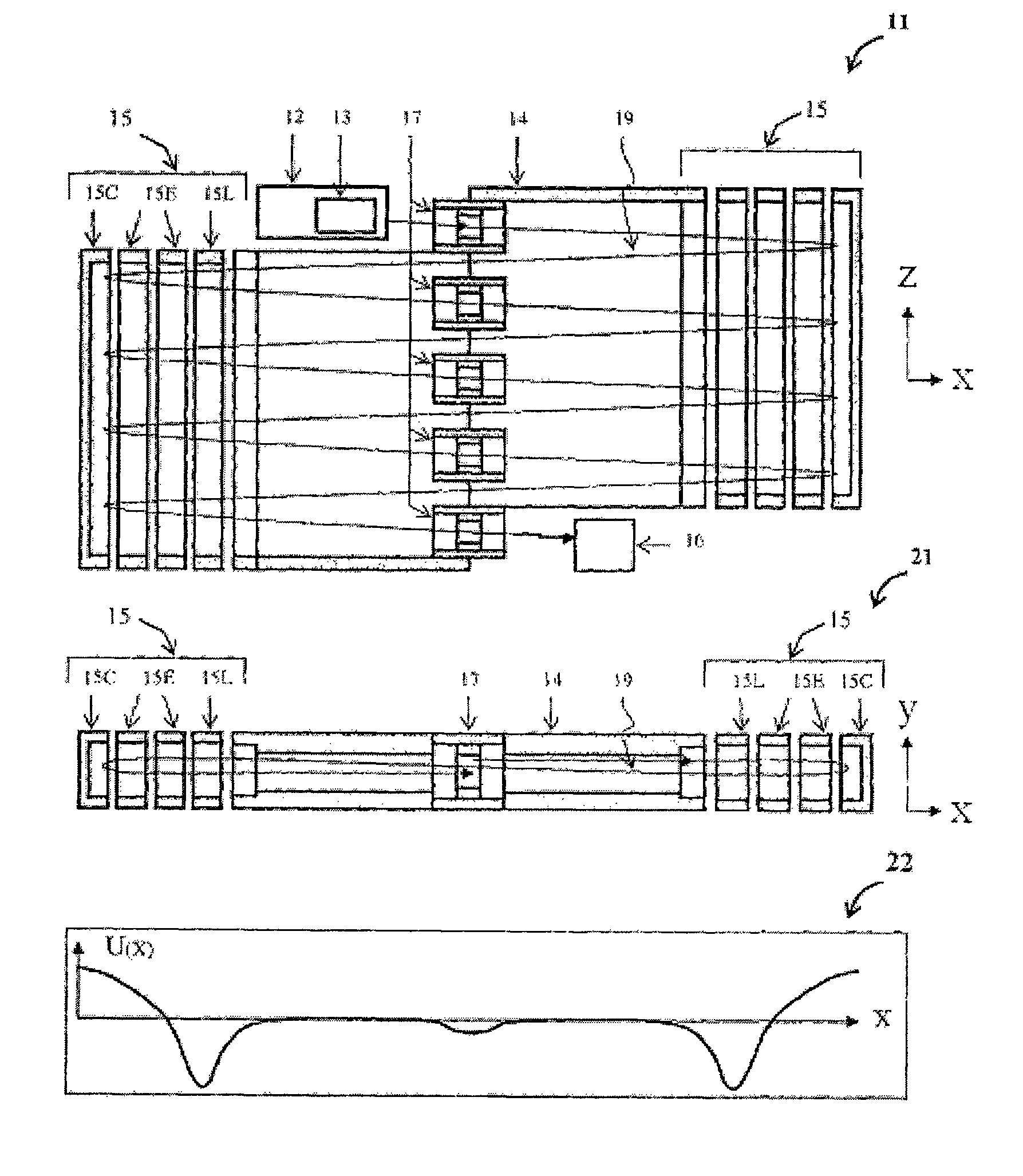
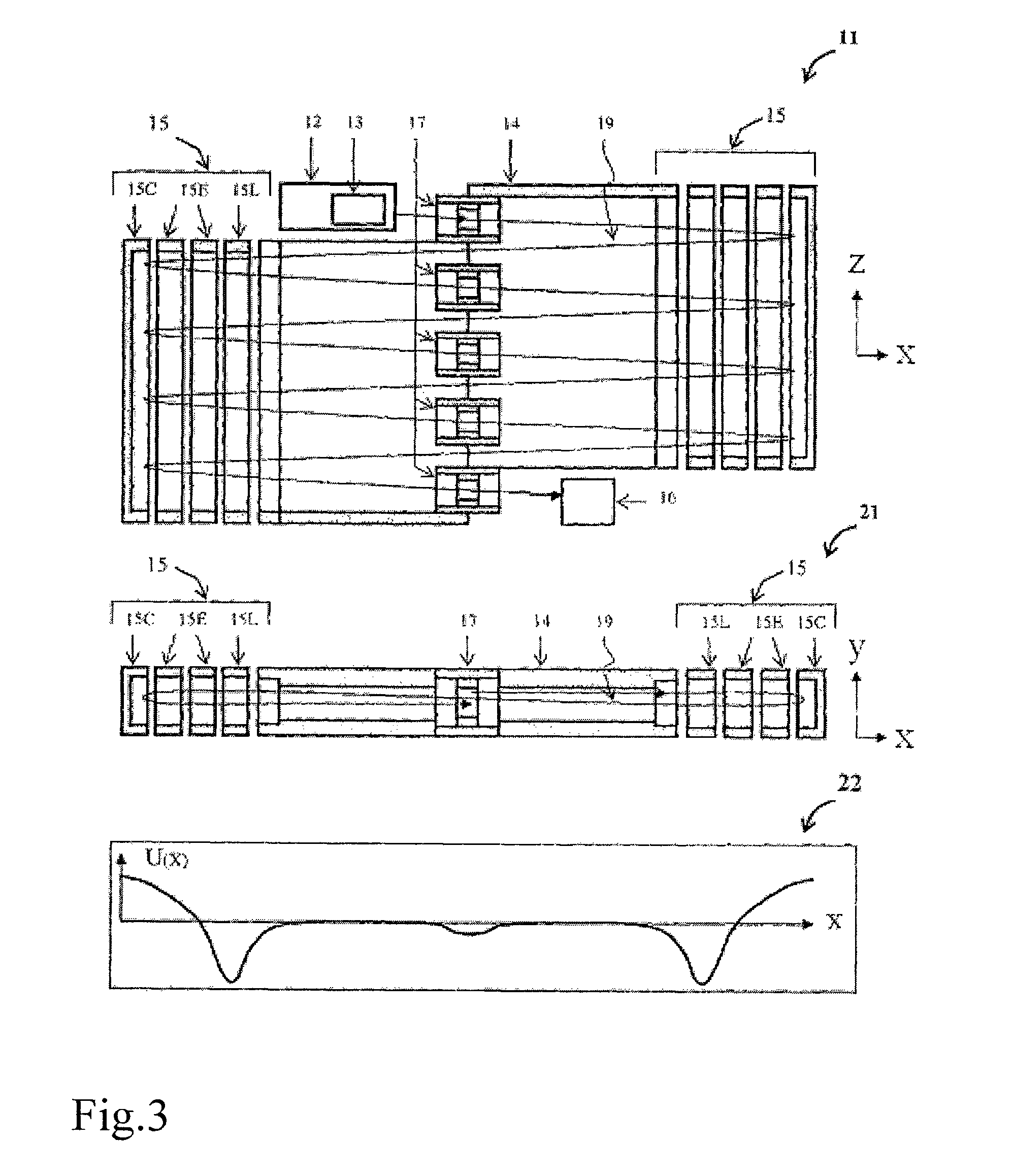
[0020]The TOF method requires the time duration (δt) of ion pulses of similar mass-to-charge (m / e) ratio to be as short as possible when they arrive at the surface of detector. This is because resolving power of mass analysis (Rm) is given by: Rm=0.5·T / δt, where T is the flight time. Detectors used in TOF mass spectrometry (e.g. MCP or Dynode Electron multipliers) usually have a flat surface where ions arrive producing several secondary electrons, which are then multiplied by an electron multiplier. Thus, the recording system actually detects a pulse of electrons when an ion arrives at the surface of the detector. Many ions of similar mass may arrive at slightly different times thus producing an averaged peak in the mass spectrum. In order to reduce (δt) it is desirable to ensure that ion packets are as narrow as possible in the direction orthogonal to the surface of detector, while in other directions the pulse can be as wide as the detector. It follows from this that it is desirab...


PUM


Abstract

A multi-reflecting ion optical device includes electrostatic field generating means configured to generate electrostatic field defined by a superposition of first and second distributions of electrostatic potential ΦEF, ΦLS. The first distribution ΦEF subjects ions to energy focusing in a flight direction and the second distribution ΦLS subjects ions to stability in one lateral direction, to stability in another lateral direction for the duration of at least a finite number of oscillations in the one lateral direction and to subject ions to energy focusing in the one lateral direction for a predetermined energy range.

Description

FIELD OF THE INVENTION[0001]This invention relates to multi-reflecting ion optical devices. The invention relates particularly, though not exclusively, to multi-reflecting time-of-flight (TOF) mass analysers; that is, TOF mass analysers having increased flight path due to multiple reflections, and to TOF mass spectrometers including such TOF mass analysers. The invention also relates to multi-reflecting ion optical devices in the form of an ion trap; for example, an electrostatic ion trap employing image current detection, an ion trap arranged to carry out mass-selective ion ejection, and an ion trap used as an ion storage device.BACKGROUND[0002]Accurate measurement of the masses of atoms and molecules (mass-spectrometry) is one of the most efficient methods for qualitative and quantitative analysis of chemical compositions of substances. The substance under investigation is first ionised using one of a number of available ionisation methods (e.g. electron impact, discharge, laser i...

Claims


Application Information

Patent Timeline
Patent Type & Authority Patents(United States)
IPC IPC(8): H01J49/40
CPCH01J49/406H01J49/4245
Inventor GOLIKOV, URIYSOLOVYEV, KONSTANTINSUDAKOV, MIKHAILKUMASHIRO, SUMIO
Owner SHIMADZU CORP
Why Eureka
Try Eureka