Catalyzed reinforced polymer composites

a technology of reinforced polymer and composites, applied in the field of catalytically reinforced polymer composites, can solve the problems of reducing the adhesion between the matrix and the fiber, affecting the performance of the composite, and requiring complex equipment and procedures, so as to reduce the crosslinking density, improve the control, and facilitate the measurement

Inactive Publication Date: 2004-06-15
THE BOARD OF TRUSTEES OF THE UNIV OF ILLINOIS
View PDF30 Cites 25 Cited by
  • Summary
  • Abstract
  • Description
  • Claims
  • Application Information

AI Technical Summary

Benefits of technology

The present invention includes a process for molding a composite using a reactive liquid and a solid activator deposited onto a reinforcing material which is placed inside the mold. The reactive liquid does not need to be mixed immediately prior to dispensing the liquid into the mold. The low viscosity of the reactive liquid allows for high fiber loadings in fiber-reinforced composite materials.
Increased reinforcement density can provide for extremely high stiffness and strength in poly(cyloolefin) composites. An important factor in achieving high fiber loadings is the viscosity of the reactive liquid. The reactive liquid preferably has a viscosity which is sufficiently low to allow the liquid to be dispensed into the mold and to completely fill the mold as well as the spaces surrounding the reinforcement phase. Preferably, the viscosity of the reactive liquid at ambient temperature is less than 100 centipoise (cps). More preferably, the viscosity of the reactive liquid at ambient temperature is less than 50 cps. Even more preferably, the viscosity of the reactive liquid at ambient temperature is less than 10 cps. Even more preferably, the viscosity of the reactive liquid at ambient temperature is less than 1.0 cps.
The mold containing the fibers is closed and then filled with the reactive liquid. Referring to FIG. 3, the mold 20 may have at least two parts 24 and 26 which, when mated together, form a mold cavity 28 containing fibers 22. The mold has an inlet sprue 30 in contact with the mold cavity through which the reactive liquid is dispensed. The mold may also have a vent sprue 32 in contact with the mold cavity through which air may be displaced from the cavity as it is filled with the reactive liquid. The vent sprue may also allow for venting or evacuation of volatile compounds which are present in the reactive liquid or which are formed during the polymerization and curing process.
Contact between the reactive liquid and the reactive fibers induces polymerization of the reactive liquid. This polymerization may also involve the curing of the polymer into a crosslinked network. Once the composite has solidified the mold is opened, and the molded composite material is removed (see FIG. 4). This process can yield composites with desirable properties without the need for mixing and metering, since no activator components need to be combined with the reactive liquid prior to dispensing. The composites formed by this process may be characterized by presence of the activator or its derivatives in the composite. The presence of ruthienium or osmium from the activator may be conveniently measured by X-ray spectroscopy.
This process also provides for improved control and more processing options in molding composites. For example, the crosslink density of a molded object can be controlled by adjusting the amount of activator that is applied to the fiber preform. A smaller amount of activator can provide for a lower crosslinking density, allowing for a more flexible molded object. In addition, the activator can be applied to the preform in a non-uniform fashion. Thus, the crosslink density can be systematically varied within a single molded object. Another advantage of this process is the ability to mold composites with high loadings of fiber reinforcement.

Problems solved by technology

Multi-component reactive liquids typically require complex equipment and procedures for storing and mixing the ingredients and for metering and dispensing the liquid into the mold.
An increased viscosity can prohibit complete filling of the mold and permeation of the preform, and this tends to decrease the adhesion between the matrix and the fibers.
Poor interfacial adhesion between the reinforcement and matrix phase can cause a material to have less than desirable stiffness and strength.
A variety of methods have been developed to alleviate this problem when using multi-component reactive liquids, but these methods generally increase the cost and complexity of the process.

Method used


Image

  • Catalyzed reinforced polymer composites
  • Catalyzed reinforced polymer composites
  • Catalyzed reinforced polymer composites

Examples


example 1

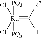
Grubbs catalyst (1.2 g) is dissolved in acetone (500 milliliters) and transferred to a spray bottle. Several layers of plain weave e-glass fabric are cut and sprayed with the catalyst solution. The fabric weighs 25 g before the solution application and 26 g after the application once the preform is dry to the touch.

A two-part aluminum-plexiglass mold with an interior of dimensions 3 cm.times.8 cm.times.0.35 cm is used for the RTM process. The lower part of the mould has, on the side at the bottom, an opening of diameter 9 mm connected to the container for the dicyclopentadiene (DCPD) by a channel. A valve is incorporated between the container and the mold. A second opening of diameter 9 mm in the middle of the upper part of the mold is vented to the atmosphere. The preform containing the reactive fibers is laid in the mold. The DCPD (10 g) is transferred into the mold by injecting it through the channel. The flow rate can be regulated by the valve setting. To obtain good impregnatio...

##ic example 1

Prophetic Example 1

A composite bar is made by the process of Example 1, except using Cl.sub.2 (P(C.sub.6 H.sub.5).sub.3).sub.2 Os(.dbd.CH--CH.dbd.C(C.sub.6 H.sub.5).sub.2) as the activator.

##ic example 2

Prophetic Example 2

A composite bar is made by the process of Example 1, except using (F.sub.3 CC(.dbd.O)O).sub.2 (P(C.sub.6 H.sub.5).sub.3).sub.2 Ru(.dbd.CH--CH.dbd.C(C.sub.6 H.sub.5).sub.2) as the activator.


PUM

PropertyMeasurementUnit
viscosityaaaaaaaaaa
volume fractionaaaaaaaaaa
viscosityaaaaaaaaaa

Abstract

A method for making a fiber-reinforced composite comprises dispensing a reactive liquid into a mold. The mold comprises fibers and a single-component activator on the fibers. The reactive liquid comprises a cyclic olefin, and the mold comprises fibers and a single-component ROMP activator on the fibers. Composites formed by the method may have high fiber densities.

Description

Reinforced composite materials are widely used as structural materials for aerospace, automotive, and construction applications. These materials can provide desirable properties, such as high stiffness and strength. Composites typically include a continuous matrix phase, usually a polymeric material or a ceramic, and a reinforcement phase. The reinforcement phase can be made of inorganic materials, including metals, ceramics, and glasses; or organic materials, including organic polymers and carbon fibers. Particularly good properties are obtained when the reinforcement phase contains fibrous materials.The manufacture of fiber-reinforced composites involves the combination of the fiber reinforcement and a liquid precursor to the matrix in a mold, followed by solidification of the liquid and formation of the matrix. This solidification can be the result of chemical reactions, in which case the liquid precursor is referred to as a reactive liquid. Alternatively, the solidification can ...

Claims


Application Information

Patent Timeline
Patent Type & Authority Patents(United States)
IPC IPC(8): C08F32/00C08J5/00C08J3/24
CPCC08F32/00C08J3/242C08J5/00
Inventor KESSLER, MICHAEL R.WHITE, SCOTT R.MYERS, BENJAMIN D.
Owner THE BOARD OF TRUSTEES OF THE UNIV OF ILLINOIS
Why Eureka
Try Eureka