
Pinch valve

a technology of pinch valve and valve body, which is applied in the direction of diaphragm valve, valve details, valve arrangement, etc., can solve the problems that the above pinch valve cannot be used as a pinch valve in the pipeline of a semiconductor manufacturing apparatus, and the adjustment of a very small flow rate cannot be performed, so as to improve the durability of the tube body and the effect of small flow ra

Inactive Publication Date: 2004-06-29
ASAHI YUKIZAI KOGYO CO LTD
View PDF6 Cites 15 Cited by
  • Summary
  • Abstract
  • Description
  • Claims
  • Application Information

AI Technical Summary

Benefits of technology

The present invention provides a pinch valve that is compact, durable, and can adjust very small flow rates. The invention achieves this by integrating a drive and a valve body, making the overall height of the valve low. The invention also includes a cylinder body with a cylinder portion, a piston, and a connecting body carrier for connecting the tube body to the valve. A spring is installed in the cylinder body and the piston has a flange portion for engagement with the connecting body carrier. The invention also includes a connecting body with an inserting portion and a pipeline connecting portion for connecting the tube body to the valve. The materials used for the tube body and the cylinder body are elastic, such as EPDM, fluororubber, or silicone rubber. The invention provides a pinch valve that is compact, durable, and can adjust very small flow rates.

Problems solved by technology

Consequently, the above pinch valve cannot be used as a pinch valve in the pipeline of a semiconductor manufacturing apparatus.
Also, since, in the pinch valve of such construction, it is difficult to optionally adjust the degree of opening the valve tube body, adjustment of a very small flow rate cannot be performed.

Method used


Image

  • Pinch valve
  • Pinch valve
  • Pinch valve

Examples


third embodiment

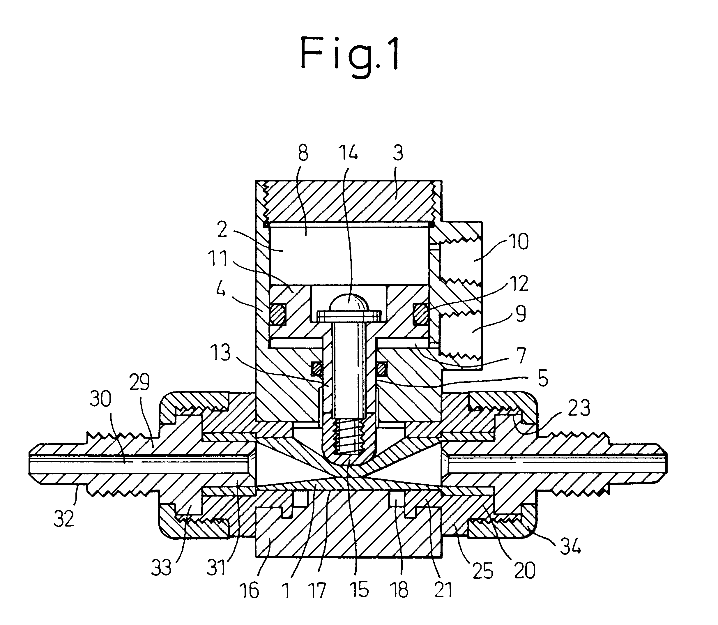
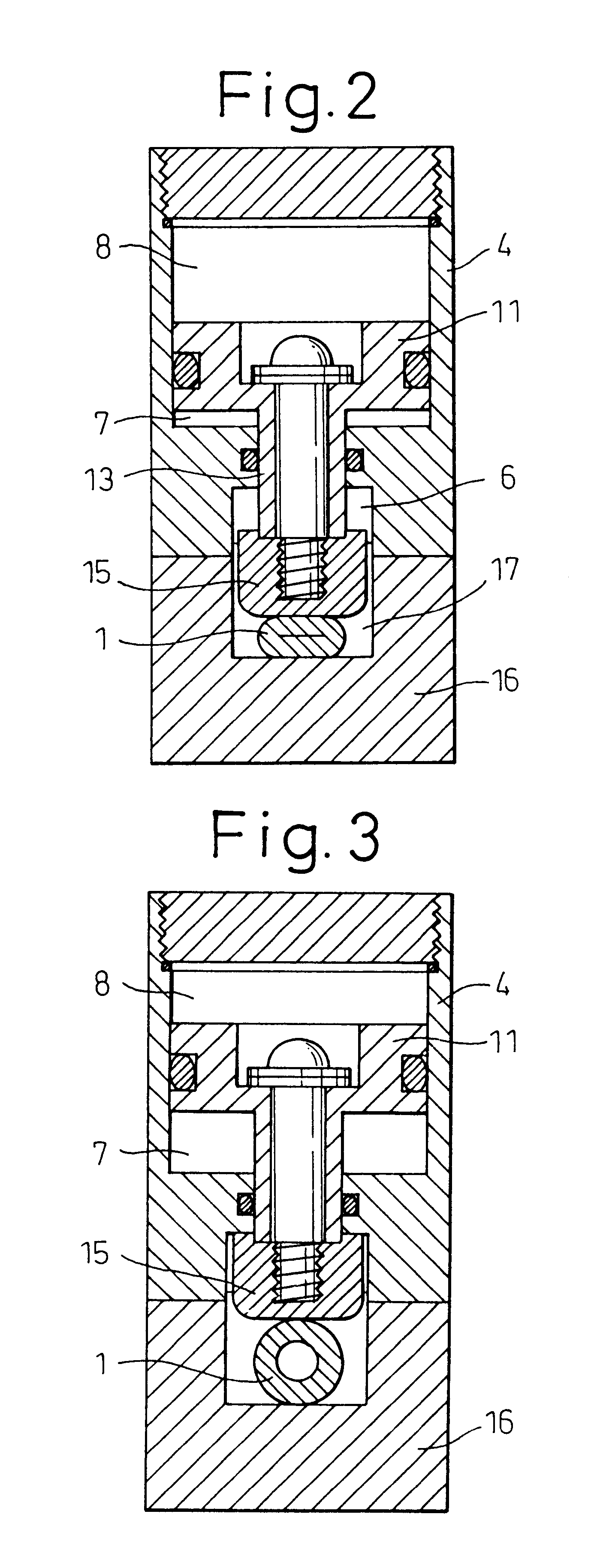
Embodiments of a first embodiment of the present inventions will now be explained. However, it should be noted that the invention is not limited to such an embodiment. FIG. 1 is a longitudinal cross section of embodiment of a pinch valve according to the first invention showing the closed condition. FIG. 2 is a longitudinal cross section viewing the pinch valve in FIG. 1 from the side (in the direction of the flow passage). FIG. 3 is a longitudinal cross section showing the opened condition of FIG. 2. FIG. 4 is a bottom view of a cylinder body in FIG. 1. FIG. 5 is a plan view of a body in FIG. 1. FIG. 6 is an exploded front view of a fixing bolt, a piston and a pressing piece. FIG. 7 is a longitudinal cross section of a connecting body carrier in FIG. 1. FIG. 8 is a right side view of the connecting body in FIG. 7. FIG. 9 is a longitudinal cross section of an another embodiment of the pinch valve according to the invention showing the closed condition. FIG. 10 is a longitudinal cros...

second embodiment

Next, a reverse operation type pinch valve which is the first invention will be explained below on the basis of FIGS. 9 to 11.

Reference numeral 35 designates a spring installed in the cylinder portion 2 in a manner such that the upper end surface of the piston 11 and the lower end surface of the cylinder cover 3 contact the spring. Although a single spring 35 is installed in this embodiment, the number of springs may be increased, depending on the urging force required.

The remaining constitution of the second embodiment is similar to the first embodiment, and thus further explanation will be omitted.

The operation of the pinch valve of the second embodiment constituted as above and the action as a reverse operating valve is as follows.

In the condition where the pinch valve is fully closed as shown in FIGS. 9 and 10, if compressed air is supplied into the first space portion 7 from the air port 9, the piston 11 begins to rise in the cylinder portion 2, with the spring 35 being compres...

first embodiment

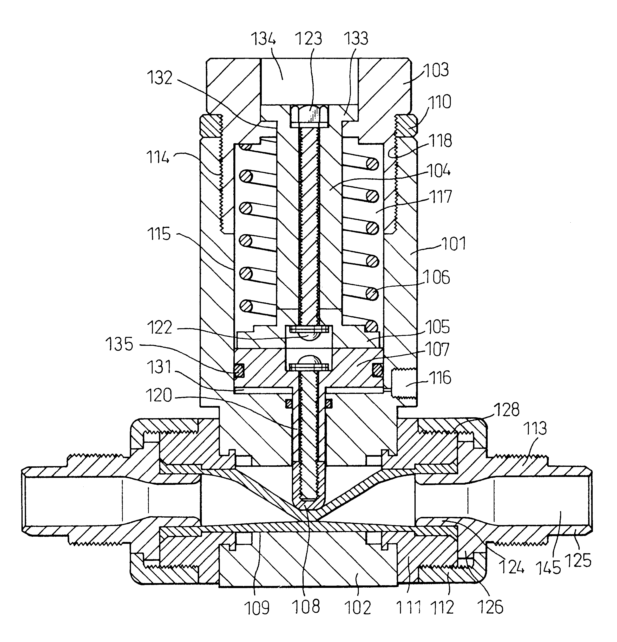
the pinch valve made of PVDF according to the second invention will be explained below on the basis of the drawings.

Reference numeral 101 designates a cylinder body in which a cylinder portion 115 having a screw portion 114 at the upper portion of the inner surface of the cylinder body is provided, the screw portion 114 being screwed into a handle 103. On the center of the lower surface of the cylinder body 101 are continuously provided a through-hole 119 penetrated by a piston connecting portion 120 and an oval slit 121 containing a pressing piece 108 (see FIG. 21). Also, on the inner peripheral side surface of the cylinder body 101 is provided an air port 116 communicating a first space portion 131 defined by the lower end surface of the cylinder portion 115, i.e., the inner peripheral and bottom surfaces of the cylinder portion 115 and the lower end surface of a piston 107 with an outside air supply device, etc. (not shown).

The handle 103 is cylindrical, and is provided with a th...


PUM


Abstract

A pinch valve of the invention comprising an elastic tube body 1, a cylinder body 4 having a cylinder portion 2 and a cylinder cover 3, a piston 11 sliding on the inner periphery of the cylinder body, a pressing piece 15 fixed to a connecting portion 13 suspended from the piston, a body 16 joined to the cylinder body and having a groove 17 receiving the tube body 1, a pair of connecting body carriers 20 engaged with grooves of the body and having a through-hole 26 receiving the tube body 1, a first and a second space portions 8, 7 formed above and under the piston 11, respectively, and a pair of air ports 10, 9 respectively communicating with the first and second space portions 8, 7.The whole pinch valve is made compact in construction.

Description

The present invention relates to a pinch valve used in a fluid transport pipeline in various industrial fields, such as chemical factories, semiconductor production, food processing, biotechnology or the like, and more particularly, to a pinch valve which is compact and mitigates the damage a tube body suffers during opening and the closing of the valve.Hitherto, various pinch valves have been proposed, and an example is disclosed in Japanese Examined Utility Model Publication No. 45-3264. According to this publication, as shown in FIGS. 27 and 28, in two upper and lower pistons 41, 42 fitted in a cylinder 40 on a leg member 39 constituted by a leg stand 37 and leg rods 38, the upper piston 41 is fixed to the upper end of a shaft rod 43 and the lower piston 42 is fixed to the upper end of a pipe shaft 44 loosely fitted on the shaft rod 43. On the lower portion of the pipe shaft 44 is provided a wing piece 45 which is fixed to a lower pressing piece 47 via connecting bars 46. On the ...

Claims


Application Information

Patent Timeline
Patent Type & Authority Patents(United States)
IPC IPC(8): F16K7/00F16K7/07F16K7/06
CPCF16K7/066F16K7/07F16K7/06
Inventor FURUKAWA, SHIGENOBUHAMADA, TAKESHI
Owner ASAHI YUKIZAI KOGYO CO LTD
Learn More