
Method and apparatus for two-dimensional absolute optical encoding

a technology of absolute optical encoding and method, applied in the direction of instruments, photoelectric discharge tubes, sensing by electromagnetic radiation, etc., can solve the problems of measurement error, measurement error, measurement error, etc., and achieve the effect of simple computational image processing

Inactive Publication Date: 2004-07-20
ADMINISTATOR OF THE NAT AERONAUTICS & SPACE ADMINISTATION UNITED STATES GOVERNMENT AS REPRESENTED BY THE
View PDF5 Cites 62 Cited by
  • Summary
  • Abstract
  • Description
  • Claims
  • Application Information

AI Technical Summary

Benefits of technology

The encoder and method according to the present invention use mature technologies such as microlithography, optical projection, CCD array image detection, and simple computational image processing. However, the specific use of a combination of such mature technologies according to the present invention allows results, such as those stated above, which were not possible through the use of heretofore known encoders.

Problems solved by technology

However, measurement errors can occur if the travel axes are not straight, flat, or orthogonal.
Measurement error can also occur if the linear encoders are not aligned properly to their directions of motion.
In the case where an axis does not travel straight, such that with the intended motion there is also movement orthogonal to the intended motion, the encoder along the orthogonal axis will not sense that movement, resulting in error in position measurement.
Therefore, the measurements can be of limited accuracy due to lack of orthogonality of mechanical alignment of axes, non-straight travels in two orthogonal axes, and mechanically coupled motions from two orthogonal axes.

Method used


Image

  • Method and apparatus for two-dimensional absolute optical encoding
  • Method and apparatus for two-dimensional absolute optical encoding
  • Method and apparatus for two-dimensional absolute optical encoding

Examples


Embodiment Construction

This invention presents a two-dimensional absolute optical encoder and a method for determining position of an object in accordance with information from the encoder. Example of a two-dimensional coordinate system is a Cartesian coordinate system, which has two orthogonal axes: X and Y. Another example of a two-dimensional coordinate system is a skew coordinate system which has two non-orthogonal axes. Another example of a two-dimensional coordinate system is a polar coordinate system which has one radial coordinate axis and one angular coordinate axis.

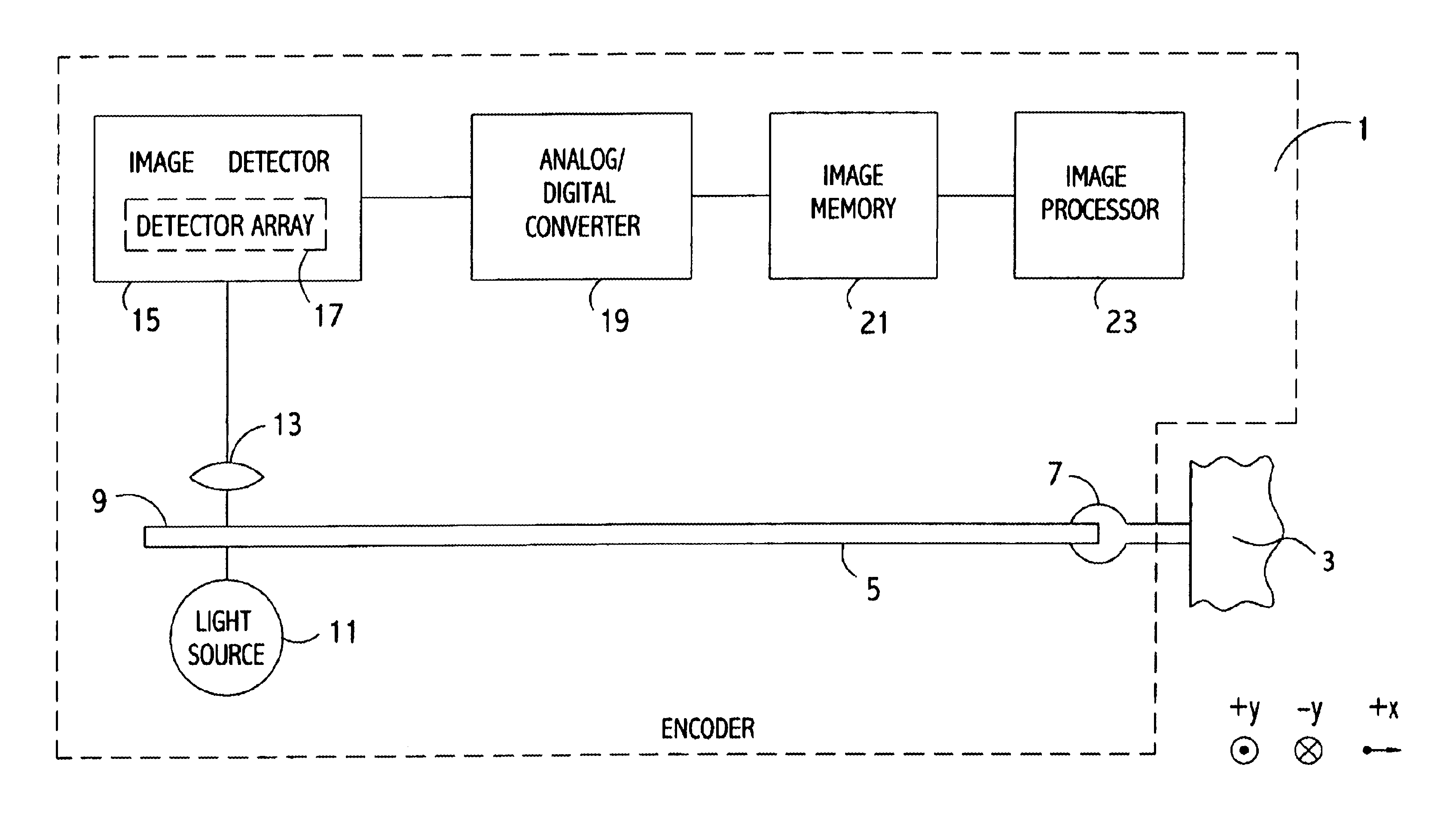
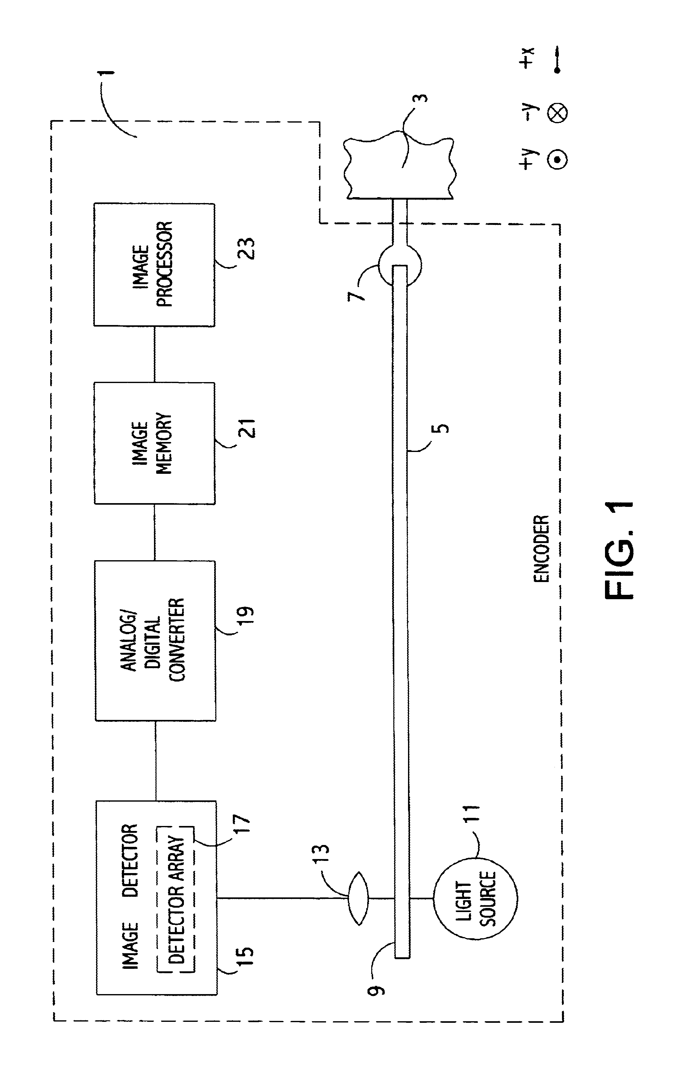
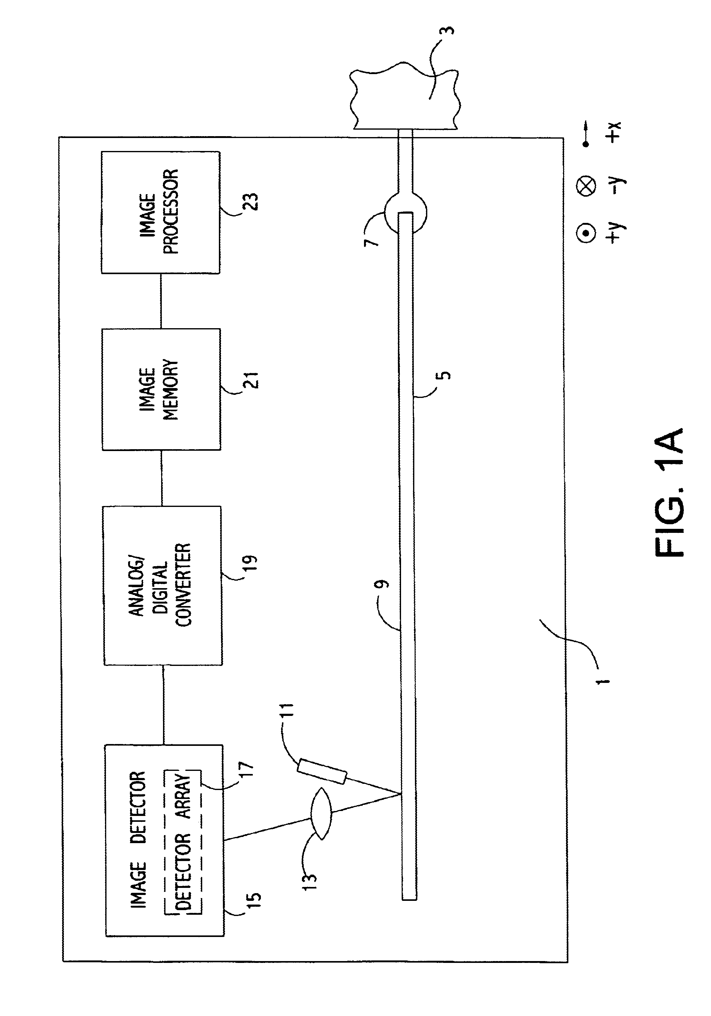
FIG. 1 shows a two-dimensional absolute encoder, in which encoder 1 determines the two-dimensional displacement of object 3, which moves in the X and Y directions. Encoder 1 includes scale 5, which is rigidly attached to object 3 by attachment 7 so that pattern 9 on scale 5, which will be described in detail below, is carefully aligned with the direction of motion of object 3. It is also possible to hold the scale fixed and to attach ...


PUM


Abstract

This invention presents a two-dimensional absolute optical encoder and a method for determining position of an object in accordance with information from the encoder. The encoder of the present invention comprises a scale having a pattern being predetermined to indicate an absolute location on the scale, means for illuminating the scale, means for forming an image of the pattern; and detector means for outputting signals derived from the portion of the image of the pattern which lies within a field of view of the detector means, the field of view defining an image reference coordinate system, and analyzing means, receiving the signals from the detector means, for determining the absolute location of the object. There are two types of scale patterns presented in this invention: grid type and starfield type.

Description

ORIGIN OF THE INVENTIONThe invention described herein was made by employees of the United States Government. The invention may be manufactured and used by or for the governmental purposes without the payment of royalties thereon or therefor.The invention is directed to a method and apparatus for, determining two-dimensional absolute position through optical encoding.A two-dimensional optical encoder measures a two-dimensional position of an object by optically detecting marks on a scale attached to the object which moves with the object. Ordinarily, when two axes of encoding are required in an application, two linear encoders, disposed orthogonal to each other, are deployed, one along each axis. However, measurement errors can occur if the travel axes are not straight, flat, or orthogonal. Measurement error can also occur if the linear encoders are not aligned properly to their directions of motion. In this case, measured travel is always less than actual travel. In the case where a...

Claims


Application Information

Patent Timeline
IPC IPC(8): G01D5/347G01D5/26
CPCG01D5/347
Inventor LEVITON, DOUGLAS B.
Owner ADMINISTATOR OF THE NAT AERONAUTICS & SPACE ADMINISTATION UNITED STATES GOVERNMENT AS REPRESENTED BY THE
Learn More