Image processing method, image processing system and display device
a technology of image processing and display device, applied in the field of image processing methods and image processing systems, can solve the problems of increasing the manufacturing cost or power consumption of the display device, and achieve the effect of simple image processing methods
- Summary
- Abstract
- Description
- Claims
- Application Information
AI Technical Summary
Benefits of technology
Problems solved by technology
Method used
Image
Examples
embodiment 1
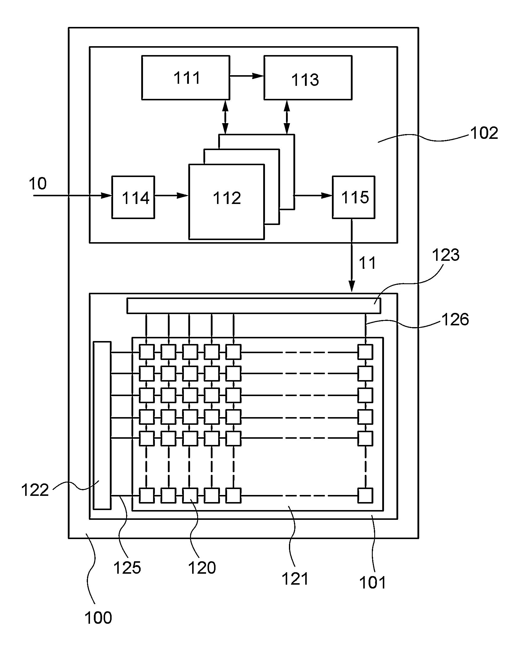
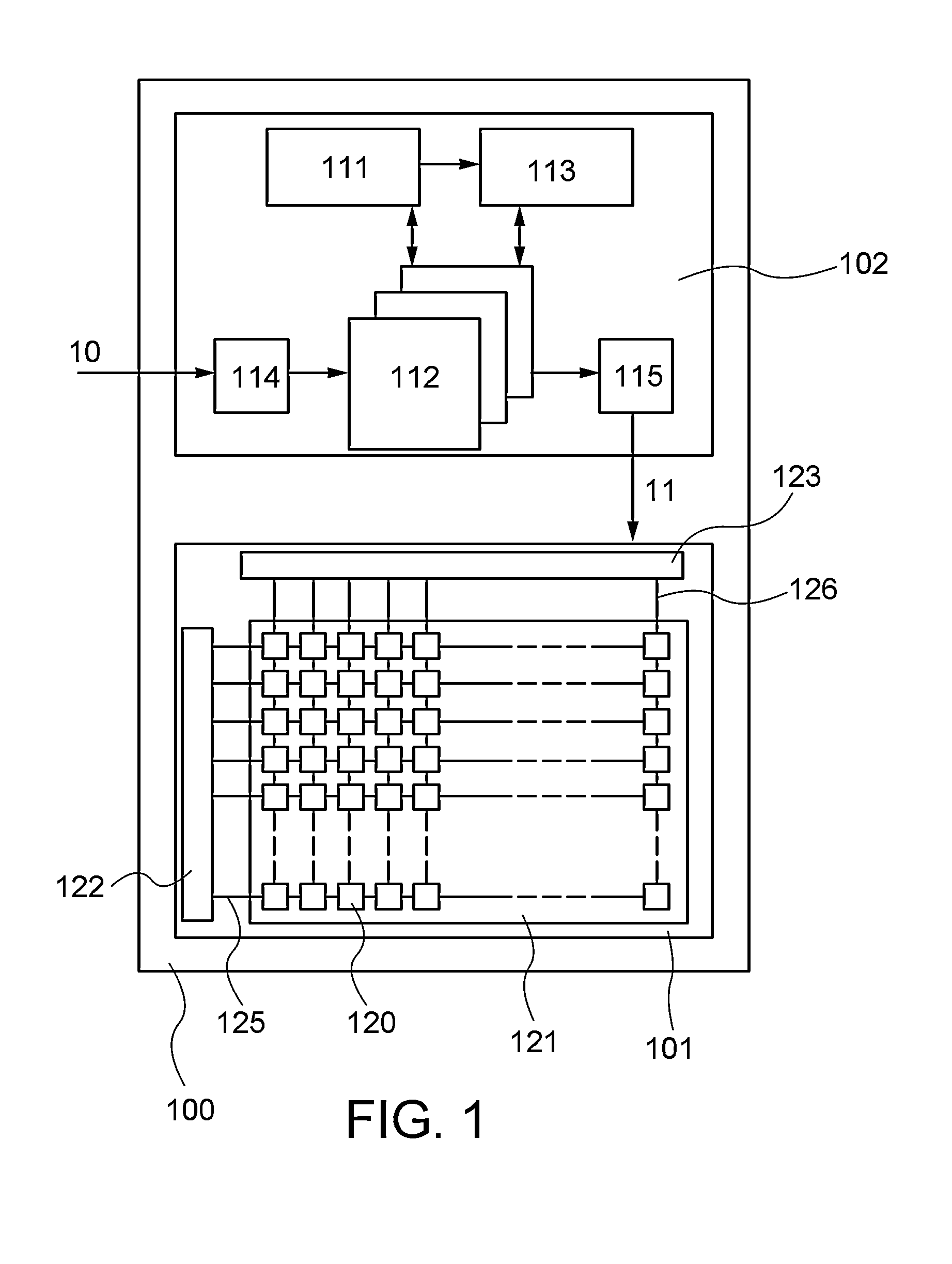
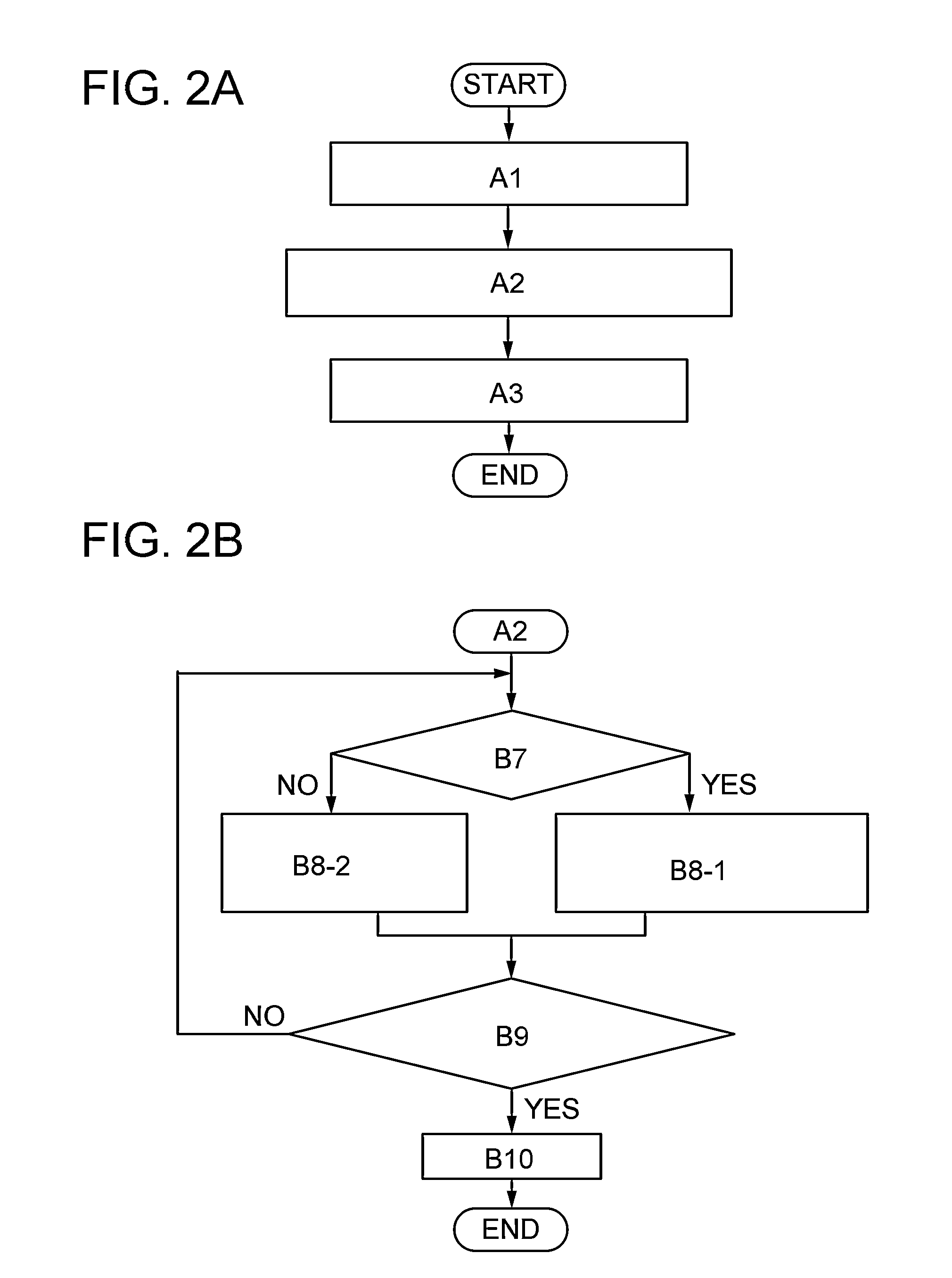
[0030]In this embodiment, an image processing method and an image processing system according to one embodiment of the present invention are described with reference to FIG. 1, FIGS. 2A and 2B, FIG. 3, FIGS. 4A to 4D, and FIG. 6A.
[0031]The image processing system according to one embodiment of the present invention includes a processing portion capable of producing a processed image by the image processing method according to one embodiment of the present invention. Examples of the image processing system according to one embodiment of the present invention include a display device that includes the processing portion and a display portion for displaying image data output from the processing portion and a storage device that includes the processing portion and a storage portion for storing image data output from the processing portion. In this embodiment, the image processing system according to one embodiment of the present invention is described giving a display device 100 illustr...
embodiment 2
[0096]Unlike in Embodiment 1, in this embodiment, an image processing method that includes the following steps is described with reference to FIG. 5 and FIG. 6B: a first step of selecting an object image and a comparison image from a plurality of frame images constituting a moving image and separating all the pixels constituting the object image into an object region and a background region; a second step of calculating an average color in the object region and calculating an inversion color from the average color; and a third step of providing the inversion color to all the pixels included in the background region at a constant rate.
[0097]In a plurality of frame images constituting a moving image, there is a portion where an image is changed in two successive frame images. In this embodiment, in a frame image, an image in which the amount of changes in motion is equal to or larger than a threshold value (or an image in which the amount of changes in motion is larger than the thresh...
example 1
[0122]In this example, a processed image produced by an image processing method according to one embodiment of the present invention is described with reference to FIGS. 7A-1 to 7D-2 and FIGS. 8A to 8C.
[0123]Table 1 shows an average color (R1, G1, B1), an inversion color (R2, G2, B2), and Δ1-2 of an image in an object region that is not subjected to image processing according to one embodiment of the present invention in each of Structure Examples 1 to 4.
[0124]In this example, the average color is an average value of gray scale values of R, G, and B in 256 grayscales of all the pixels included in the object region.
TABLE 1AverageColor in Object RegionInversion Color(R1, G1, B1)(R2, G2, B2)Δ1-2Structure Example 1(231, 226, 221)(24, 29, 34)591Structure Example 2(184, 169, 155)(71, 86, 100)251Structure Example 3(149, 140, 139)(106, 115, 116)91Structure Example 4(238, 236, 235)(17, 19, 20)653Note that Δ1-2 satisfies Equation (2).
Δ1-2=|R1+G1+B1−(R2+G2+B2)| (2)
PUM
 Abstract
Description
Claims
Application Information
 - R&D
- Intellectual Property
- Life Sciences
- Materials
- Tech Scout
- Unparalleled Data Quality
- Higher Quality Content
- 60% Fewer Hallucinations
Browse by: Latest US Patents, China's latest patents, Technical Efficacy Thesaurus, Application Domain, Technology Topic, Popular Technical Reports.
© 2025 PatSnap. All rights reserved.Legal|Privacy policy|Modern Slavery Act Transparency Statement|Sitemap|About US| Contact US: help@patsnap.com


