Method for smelting high-nitrogen steel by compression electroslag furnace

A pressurized electroslag and high-nitrogen steel technology, which is applied in the field of smelting high-nitrogen steel, can solve problems such as uneven distribution of nitrogen, and achieve the effects of simple process, avoiding secondary remelting, and uniform composition

Inactive Publication Date: 2008-09-10
NORTHEASTERN UNIV
View PDF0 Cites 36 Cited by
  • Summary
  • Abstract
  • Description
  • Claims
  • Application Information

AI Technical Summary

Problems solved by technology

It solves the problem of uneven distribution of nitrogen in the process of preparing high-nitrogen steel using the original technology, thereby avoiding secondary remelting, saving production costs, and the process method is simple and the smelting effect is good

Method used


Image

  • Method for smelting high-nitrogen steel by compression electroslag furnace
  • Method for smelting high-nitrogen steel by compression electroslag furnace
  • Method for smelting high-nitrogen steel by compression electroslag furnace

Examples


Embodiment 1

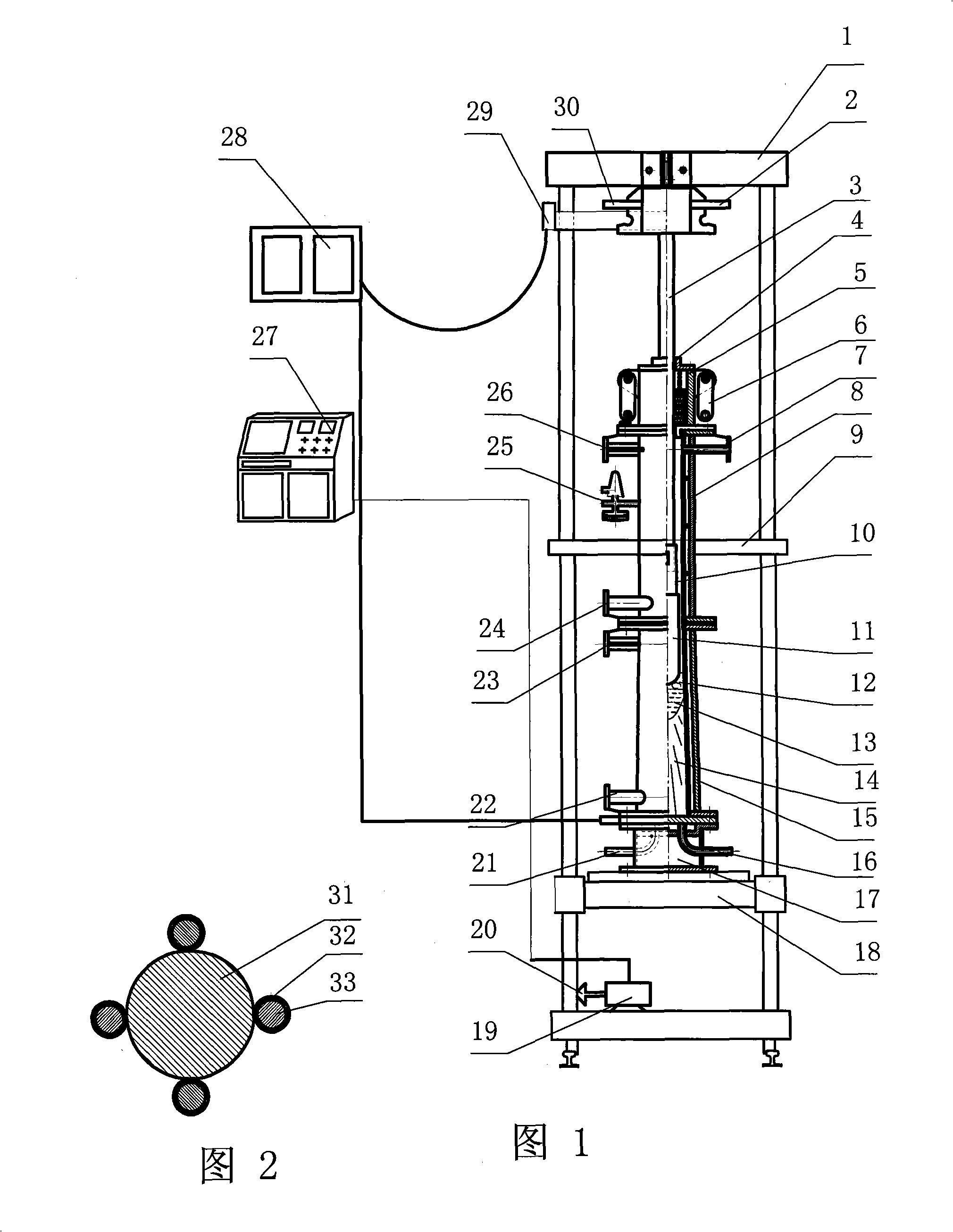
[0030] Embodiment 1: as shown in Figure 1, the present invention comprises sealing device 5, is provided with the electrode 3 that is connected with its sliding sealing in sealing device 5, is equipped with smelting chamber 8 below sealing device 5, is housed below smelting chamber 8 Crystallizer 15, bottom water tank 17 is housed below crystallizer 15, is contained on the trolley lifting platform 18 below bottom water tank 17. The upper end of the electrode 3 is welded on the cross-arm beam 1, and a conductive connector 29 is welded on the electrode 3. The conductive connector 29 is connected to one end of the water-cooled cable, and the other end of the water-cooled cable is connected to the AC power supply 28. The electrode cooling water inlet 2 and the electrode cooling water outlet 30 are welded on the side, and the lower end of the electrode 3 is a dummy electrode 10 , and the consumable composite electrode 11 is welded at the lower end of the dummy electrode 10 . A safe...

Embodiment 2

[0060] Example 2: Target steel for smelting 0Cr17.5Mn14.5Mo3.2N1

[0061] 1. Through the calculation formula

[0062] lg [ % N ] = 1 2 lg ( p N 2 / p 0 ) - 188 T - 1.17 - { ( 3280 T - 0.75 ) ( 0.13 [ % N ] + 0.118 [ % C ] + 0.043 [ % Si ] +

[0063] 0.011 [ % Ni ] + ...

Embodiment 3

[0071] Example 3: Target steel for smelting 0Cr23Mo2Ni1N1

[0072] 1. Through the calculation formula

[0073] lg [ % N ] = 1 2 lg ( p N 2 / p 0 ) - 188 T - 1.17 - { ( 3280 T - 0.75 ) ( 0.13 [ % N ] + 0.118 [ % C ] + 0.043 [ % Si ] +

[0074] 0.011 [ % Ni ] + 3...


PUM

PropertyMeasurementUnit
particle diameteraaaaaaaaaa
elongationaaaaaaaaaa

Abstract

The invention relates to a method for smelting the high-nitrogen steel by pressurizing an electroslag furnace. The method comprises the following steps that: the content and the weight percentage of each raw material of a self-consuming combined electrode parent metal are determined; the self-consuming electrode parent metal is smelted, an alloy pipe after charged with nitro-alloy particles and a deoxidizing agent is welded on the parent metal to produce the self-consuming combined electrode which is welded on a fake electrode and is clamped on the electrode; an arc starting agent is placed into a bottom water tank below the self-consuming electrode; the slag is dried for three to ten hours and is poured into a crystal device, a smelting chamber is sealed; under the condition of nitrogen, the slag is melted with a current ranging from 1000 to 2000A; afterwards, the pressure of the smelting chamber and the cooling water are increased to be 3 to 10 MPa, the smelting is performed with a current ranging from 2000 to 6000A; when the smelting current is reduced to 1000 A, the smelting is over. The method has the advantages that the solid state arc starting slagging way and the self-consuming combined electrode are adopted to perform the smelting in an over-normal pressure sealing smelting chamber, and the problem of the prior art of uneven distribution of nitrogen in the process of preparing high-nitrogen steel is solved, thereby avoiding the remelting and saving the production cost; moreover, the technique method is simple and the smelting effect is good.

Description

technical field [0001] The invention relates to a method for smelting high-nitrogen steel, in particular to a method for smelting high-nitrogen steel using a pressurized electroslag furnace. Background technique [0002] As an interstitial element in steel, nitrogen can improve various properties of steel, including strength, toughness, creep resistance, wear resistance, etc. performance, corrosion resistance, etc. In a broad sense, the so-called "high nitrogen steel" refers to the steel whose actual nitrogen content in the material exceeds the limit value that can be achieved by preparing the material under normal pressure (0.1MPa). It is generally believed that according to the content of nitrogen in austenitic stainless steel, nitrogen-containing austenitic stainless steel can be divided into nitrogen-controlling type (nitrogen content 0.05% ~ 0.10%), medium nitrogen type (nitrogen content 0.10% ~ 0.40%) and high nitrogen type. Nitrogen type (nitrogen content above 0.40...

Claims


Application Information

Patent Timeline
Patent Type & Authority Applications(China)
IPC IPC(8): C22B9/18
Inventor 姜周华曹阳李花兵侯治波
Owner NORTHEASTERN UNIV
Why Eureka
Try Eureka