Image display device and method

Active Publication Date: 2006-12-21
SEIKO EPSON CORP
View PDF27 Cites 13 Cited by
  • Summary
  • Abstract
  • Description
  • Claims
  • Application Information

AI Technical Summary

Benefits of technology

[0009] An advantage of some aspects of the invention is to achieve a desired image display by a re

Problems solved by technology

However, since the range of brightness that can be displayed (dynamic range) is narrow due to light leakage or stray light generated at various optical components that constitute the optical system, it is difficult to improve the quality of the image.
However, there is a problem such that when another different image supply device is connected thereto, since the γ correction process for the image signal is also different, mismatch with the γ characteristics of the liquid crystal projector may occur, and consequently, a desired image display cannot be achieved.
In particular, the liquid crystal proje

Method used


Image

  • Image display device and method
  • Image display device and method
  • Image display device and method

Examples


Embodiment Construction

[0029] Referring now to the drawings, an embodiment of the invention will be described. As an example of an image display device employing tan image display method of the invention, a three-panel liquid crystal projector provided with liquid crystal light valves for each different R, G and B colors will be described.

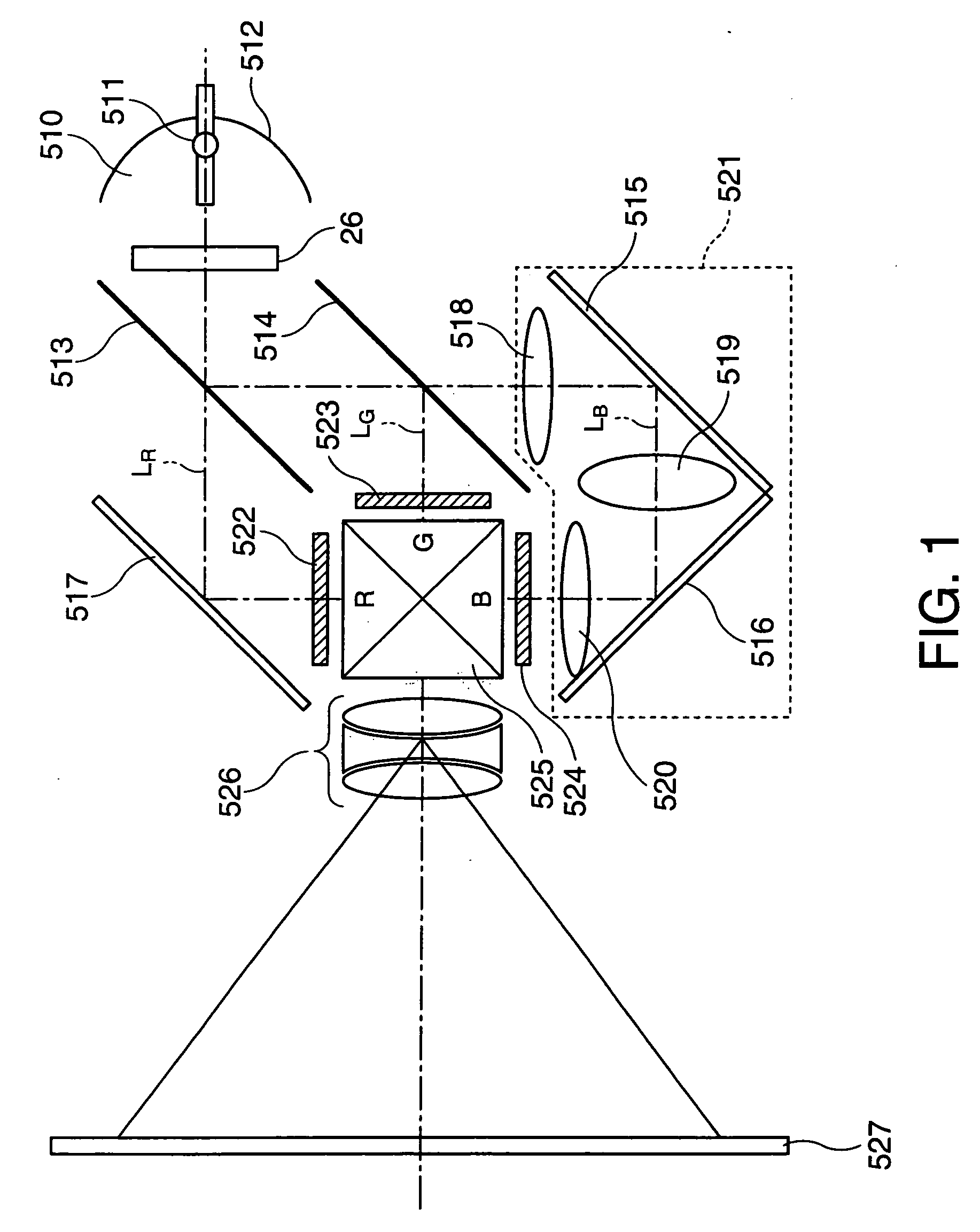
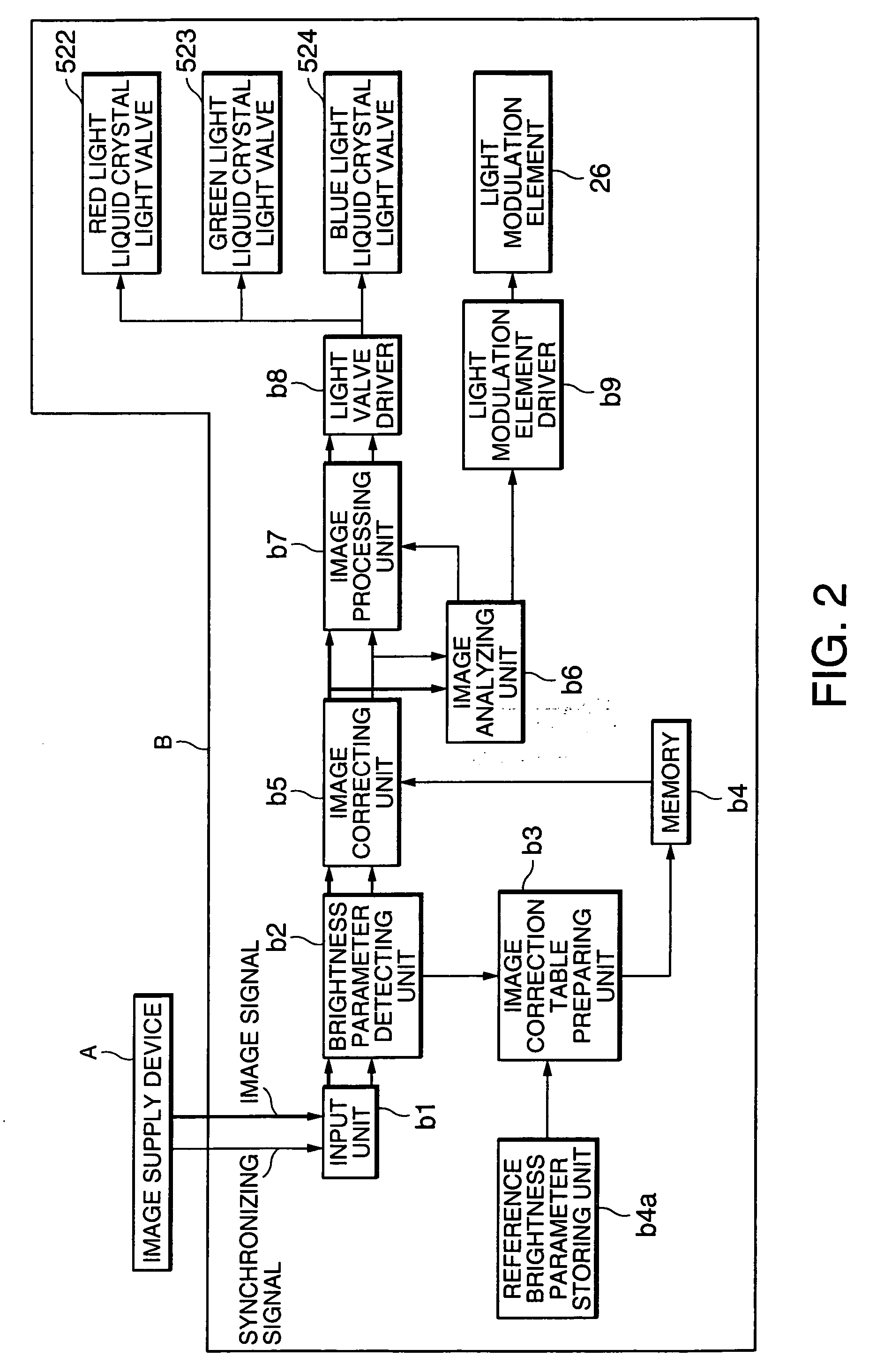
[0030]FIG. 1 is a schematic block diagram showing an example of a liquid crystal projector. As shown in FIG. 1, the liquid crystal projector includes a light source 510, a light modulation element 26, dichroic mirrors 513, 514, reflection mirrors 515, 516, 517, relay lenses 518, 519, 520, a red light liquid crystal light valve 522, a green light liquid crystal light valve 523, a blue light liquid crystal light valve 524, a cross-dichroic prism 525 and a projection lens system 526.

[0031] The light source 510 includes a lamp 511 such as an extra-high pressure mercury lamp and a reflector 512 for reflecting light from the lamp 511. Arranged between the light source 510 an...


PUM


Abstract

An image display device for displaying an image on the basis of an image signal supplied from an image supply device includes a brightness detecting section that detects a gray level which characterizes brightness of a predetermined pattern image from a pattern image signal when the predetermined pattern image is supplied from the image supply device; a storing section that stores a reference gray level predetermined in the pattern image; a correction parameter setting section that sets a correction parameter for compensating by a difference between the gray level detected by the brightness detecting section and the reference gray level stored in the storing section; and a correcting section that corrects the brightness of the image signal supplied from the image supply device on the basis of the correction parameter.

Description

BACKGROUND [0001] 1. Technical Field [0002] The present invention relates to an image display device and a method of displaying the image. [0003] 2. Related Art [0004] In association with development of IT technology in the recent years, a need of image display devices is increased in various fields. Among such image display devices, a liquid crystal projector that projects an image emitted from an optical system using a liquid crystal light valve onto a screenvia a projection lens in an enlarged scale is widely used as a mode of a liquid crystal display device that can change optical characteristics by electrically controlling an array of liquid crystal molecules. [0005] The liquid crystal projector employs the liquid crystal light valve as light modulating means. However, since the range of brightness that can be displayed (dynamic range) is narrow due to light leakage or stray light generated at various optical components that constitute the optical system, it is difficult to imp...

Claims


Application Information

Patent Timeline
IPC IPC(8): G02F1/1335
CPCG09G3/20G09G2320/0276H04N9/3194G09G2320/0693G09G2360/16G09G2320/0646
Inventor YOSHIDA, SHOHEITOYOOKA, TAKASHIIISAKA, HIDEHITO
Owner SEIKO EPSON CORP
Why Eureka
Try Eureka