
Attachment means for attaching a wheelchair to a motorized apparatus

a technology for attaching means and motorized devices, which is applied in the direction of electric propulsion mounting, wheelchair/patient conveyance, cycles, etc., can solve the problems of increasing weight, affecting the ability of users to propel when the power assist is disengaged, and devices that require excessive intervention

Inactive Publication Date: 2004-07-27
SAWYER GEORGE S
View PDF29 Cites 71 Cited by
  • Summary
  • Abstract
  • Description
  • Claims
  • Application Information

AI Technical Summary

Benefits of technology

"The present invention is about a new power system for manually operated wheelchairs that can be easily attached and detached without the need for tools or intervention on the part of the user or others. The invention solves the problem of requiring attachment to the wheelchair by adding brackets, clamps, or other attachment methods that can damage or limit the lifespan of the wheelchair. The invention also addresses the issue of requiring excessive intervention or a second party to prepare the wheelchair and propulsion device for addition of the power system. The invention allows for easy engagement and disengagement as a function of power demand and is less cumbersome to attach and detach. Overall, the invention improves the convenience and accessibility of powered wheelchairs for users."

Problems solved by technology

Throughout the prior art, one sees devices that require excessive intervention either by the user or a second party to prepare the propulsion device or the wheelchair for addition of a drive mechanism.
Adding a power assist unit to a manual wheelchair will increase the weight of the wheelchair and may offset the distribution of mass or balance and center of gravity, possibly making it more difficult for the user to propel when the power assist is disengaged.
Some of the units are cumbersome to attach and detach, requiring the assistance of a second person.
This method of attaching the tractor to the wheelchair produces an extremely low overall center of gravity in the resulting combined assembly.
Transferring to a scooter can be quite challenging and uncomfortable for the user and can lead to mishaps.

Method used


Image

  • Attachment means for attaching a wheelchair to a motorized apparatus
  • Attachment means for attaching a wheelchair to a motorized apparatus
  • Attachment means for attaching a wheelchair to a motorized apparatus

Examples


Embodiment Construction

Referring now to Table 1, shown are measurements of key physical wheel spacing and tire attributes of various wheelchairs in general use. The table reveals broad variations in height, width, wheel diameter, and attribute interrelationships that exist among conventional manually operated wheelchairs.

Table 1 shows a broad sampling of 23 different commercially available wheelchairs and provides key physical measurements, in inches, of specific attributes of each chair. The wide variations displayed in Table 1 are significant. The existence of these variations among wheelchair models has heretofore presented a significant challenge to manufacturers of devices intended for adding a motive power to conventional wheelchairs.

The sampling of conventional manually operated wheelchairs is representative of a substantial majority of all manual wheelchairs currently in use. The sampling excludes specialized manually operated wheelchairs designed specifically for small children, obese persons, or...


PUM


Abstract

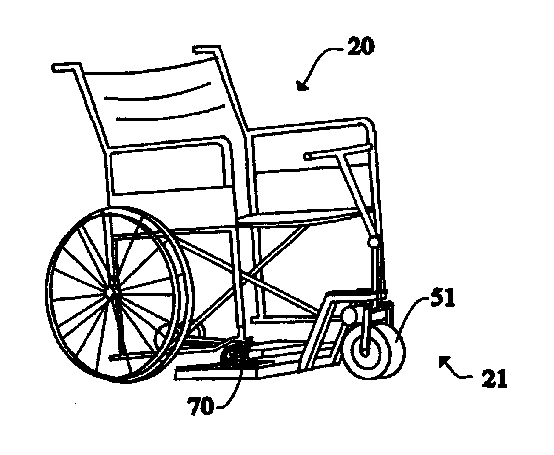
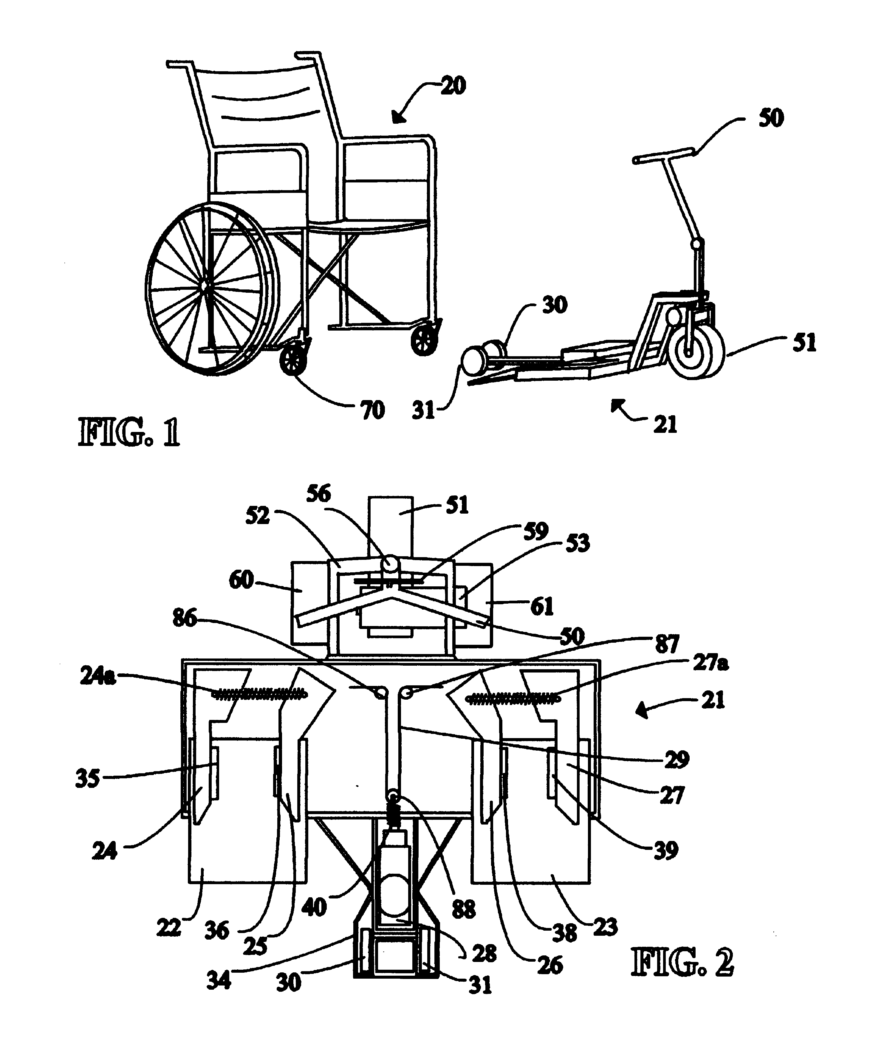
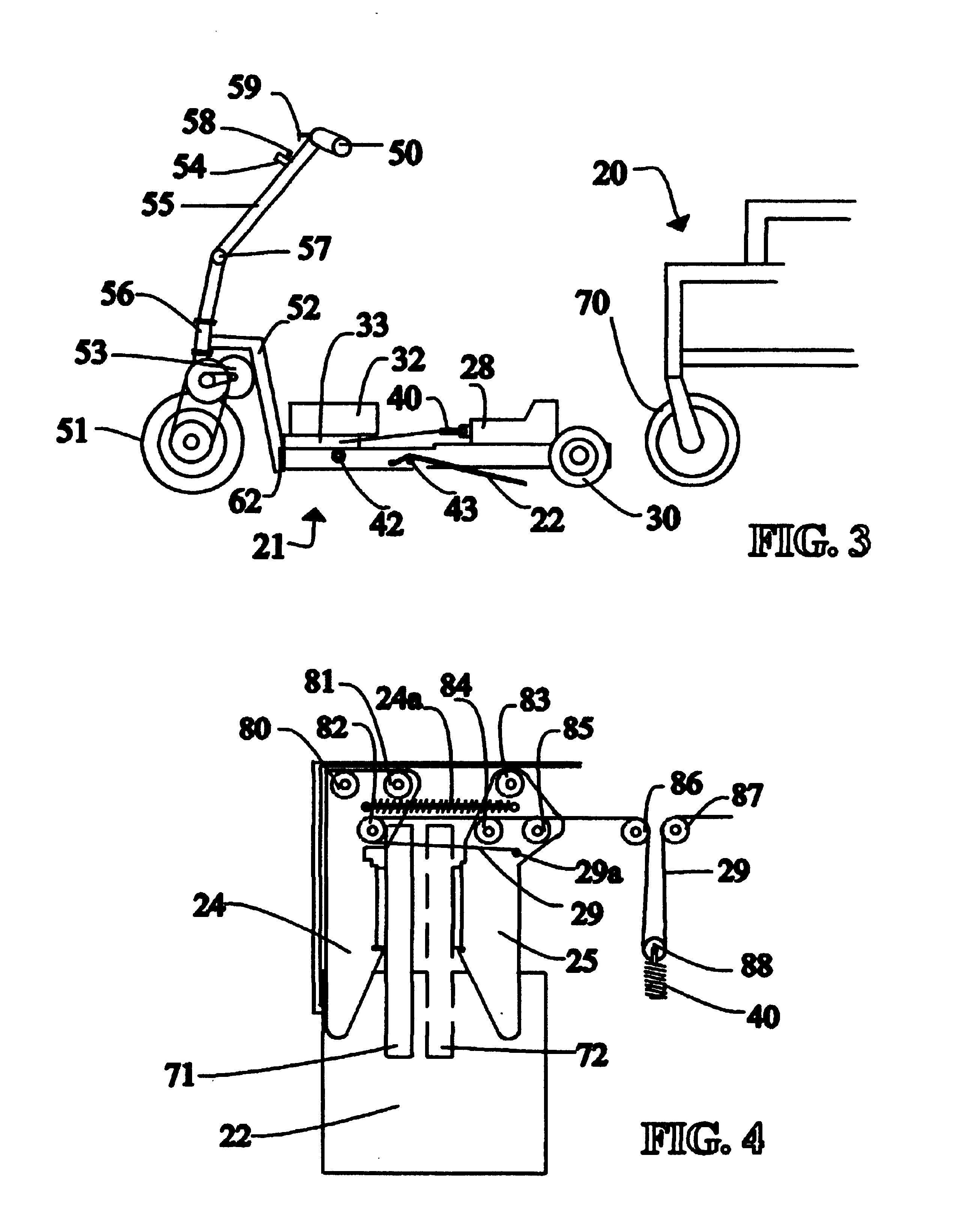
A powered propulsion apparatus that is attachable to and detachable from, a wide range of conventional wheelchairs without modification of the propulsion apparatus or the wheelchairs. The propulsion apparatus converts a conventional manually powered wheelchair into a power driven wheelchair. The apparatus clamps to the front wheels of a conventional wheelchair with a clamping mechanism that is adjustable to accommodate a wide range of wheel-spacings and wheel sizes and accommodates an inexactitude of alignment between the clamps and the wheelchair. The clamping mechanism secures the wheel chair to the propulsion apparatus without damage or stress to the wheelchair components.

Description

1. Field of UseThe present invention relates to power units used to drive manually operated conventional wheelchairs, and more particularly, to novel power units that are automatically operated from a control switch to be attachable to and detachable from conventional wheelchairs for producing power driven wheelchairs.Attachable power systems for manually operated wheelchairs are well known in the art. Various configurations have been designed with a variety of attachment methods, control methods, and detachment methods that allow the wheelchair to be converted back to a conventional manually operated wheelchair.In all instances of prior art design known to the inventor the conventional wheelchair must be fitted with brackets, clamps, bars or sockets, or the apparatus must be pre-sized and manually configured to be custom fitted to a particular variant of a conventional manually operated wheelchair. In particular instances, the rear wheels must be removed to add specialized hubs, or...

Claims


Application Information

Patent Timeline
Patent Type & Authority Patents(United States)
IPC IPC(8): A61G5/04A61G3/00A61G5/00A61G3/08A61G5/02
CPCA61G5/047A61G3/0808A61G5/02A61G2005/1051A61G2220/145A61G5/1051
Inventor SAWYER, GEORGE S.
Owner SAWYER GEORGE S
Learn More