Method for measuring flow within an open tube

a flow measurement and open tube technology, applied in the direction of measurement devices, instruments, scientific instruments, etc., can solve the problems of difficult inserting foreign matter, mechanical error may occur in a measurement value, and wear and tear of filaments

Inactive Publication Date: 2004-08-24
TSUDA TAKAO +2
View PDF8 Cites 10 Cited by
  • Summary
  • Abstract
  • Description
  • Claims
  • Application Information

AI Technical Summary

Problems solved by technology

However, in the conventional methods of measuring flow within an open tube, the first and second methods have a problem such that a mechanical error may occur in a measurement value.
The third method has a problem that the filaments are worn out and cut.
The fourth method has problems such that, since a foreign matter is inserted into a passage, it is difficult to insert the foreign matter and that the passage is contaminated due to the insertion of the foreign matter.
Consequently, any of the methods is not suitable for the separation analysis field, chemosynthesis field, and the like.

Method used


Image

  • Method for measuring flow within an open tube
  • Method for measuring flow within an open tube
  • Method for measuring flow within an open tube

Examples


example 2

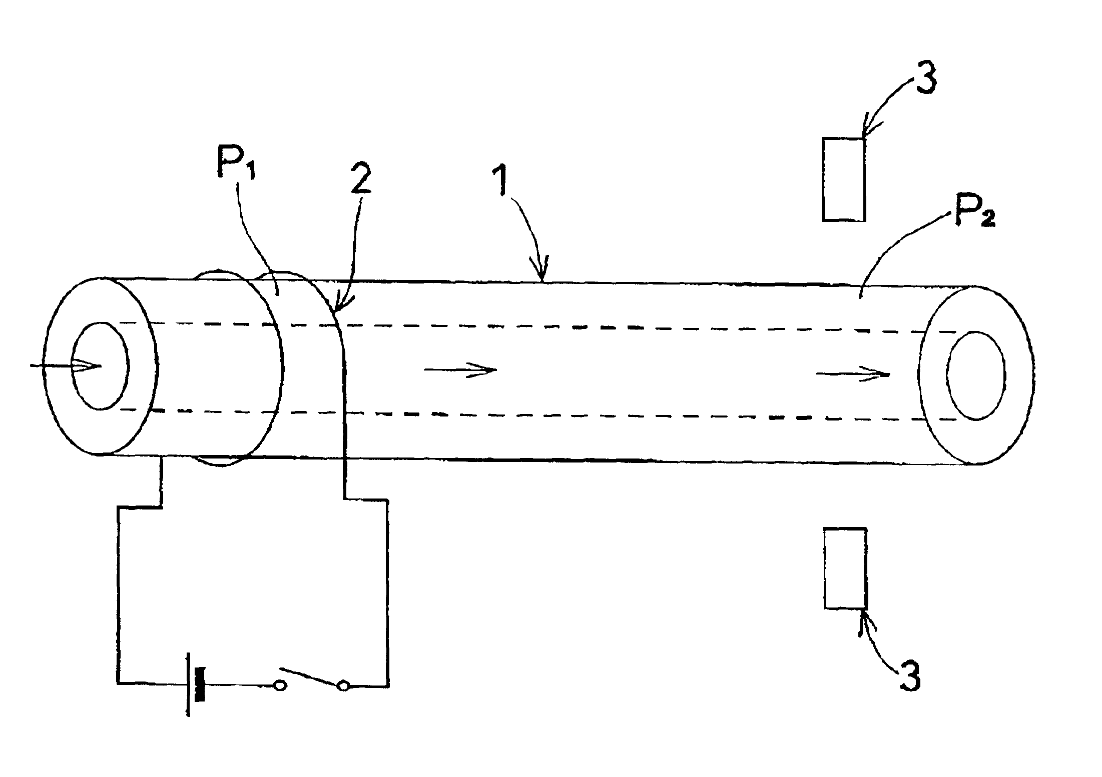
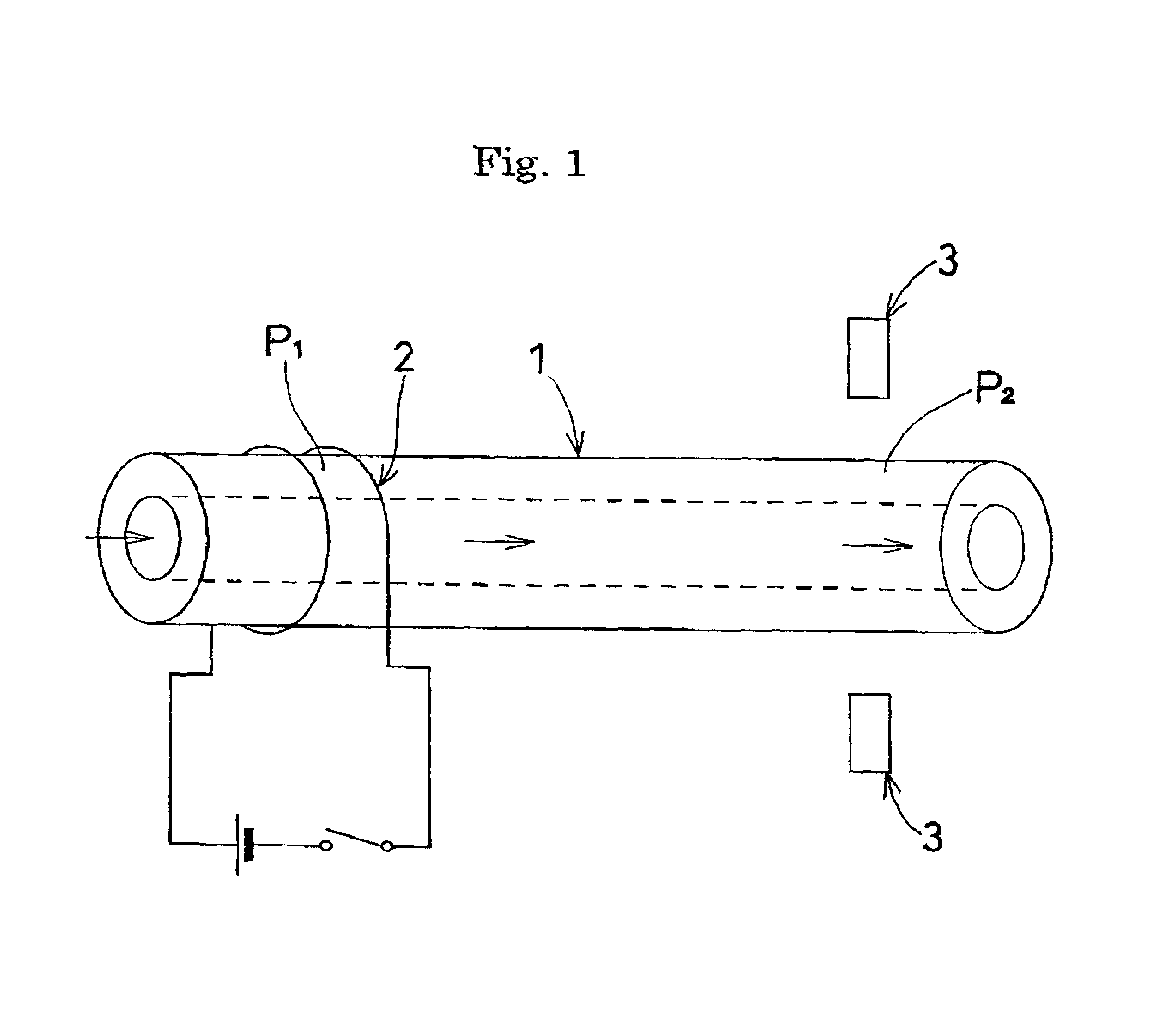
FIG. 5 shows the result of successively measuring absorbance when, in the apparatus shown in FIG. 1, the inside diameter of the open tube 1 was set to 100 .mu.m, the spacing between the portion P1 in the upstream part of the open tube 1 and the portion P2 in the downstream part of the open tube 1 was set to 30 mm, and a direct current of 0.41 A was supplied to a nichrome wire wound around the open tube 1 at a voltage of 1.2V for eight seconds. It is understood from FIG. 5 that the change in absorbance caused by bubbles generated from the fluid was detected in one minute. As a result, the flow of the liquid passing through the open tube 1 could be calculated as 235 nl / min.

example 3

FIG. 6 shows the result of measuring absorbance when, in the apparatus shown in FIG. 1, the inside diameter of the open tube 1 was set to 100 .mu.m, the spacing between the portion P1 in the upstream part of the open tube 1 and the portion P2 in the downstream part of the open tube 1 was set to 30 mm, and a direct current of 0.31 A was supplied to a nichrome wire wound around the open tube 1 at a voltage of 1.0V for 15 seconds. It is understood from FIG. 6 that the change in absorbance due to increase in temperature of the fluid was detected in one minute. As a result, the flow of the liquid passing through the open tube 1 could be calculated as 235 nl / min.

example 4

FIG. 7 shows the result of measuring absorbance when, in the apparatus shown in FIG. 1, the inside diameter of the open tube 1 was set to 100 .mu.m, the spacing between the portion P1 in the upstream part of the open tube 1 and the portion P2 in the downstream part of the open tube 1 was set to 30 mm, and a direct current of 0.36 A was supplied to a nichrome wire wound around the open tube 1 at a voltage of 1.1V for 20 seconds. It is understood from FIG. 7 that the change in absorbance due to the increase in temperature of the fluid was detected in 2.5 minutes. As a result, the flow of the liquid passing through the open tube 1 could be calculated as 94 nl / min.


PUM

PropertyMeasurementUnit
diameteraaaaaaaaaa
physical propertiesaaaaaaaaaa
optical detectoraaaaaaaaaa

Abstract

A change in physical properties of a fluid within an open tube which is caused by heating an arbitrary portion in the open tube by heating means is detected by using a detector disposed with a predetermined spacing from the arbitrary portion, thereby measuring the flow in the open tube. The present invention provides a method for measuring flow within an open tube, in which a mechanical error and contamination of a passage do not occur, as a method for measuring flow within an open tube having a very small diameter provided for the separation analysis field and chemosynthesis field.

Description

BACKGROUND OF THE INVENTION AND DESCRIPTION OF RELATED ARTThe present invention relates to flow measuring method suitable for measurement of flow within an open tube having a very small diameter, which may be provided for a separation analysis field such as liquid chromatography and electrochromatography, a chemosynthesis field, and the like.Conventionally, the flow within an open tube having a very small diameter is measured by methods such as: a first method of calculating volume of a discharge portion of a pumping device; a second method of attaching a fan to a passage and calculating the flow from the revolution of the fan; a third method of inserting two filaments, heating one of them, and calculating the flow from speed of conduction of heat to the other filament; and a fourth method of intermittently passing a substance different from a fluid, such as bubbles, into a passage and converting pass time into flow by using an optical sensor.However, in the conventional methods of ...

Claims


Application Information

Patent Timeline
Patent Type & Authority Patents(United States)
IPC IPC(8): G01N30/00G01F1/704G01F1/708G01N30/32G01F1/7084
CPCG01F1/7084G01N30/32G01N2030/324
Inventor TSUDA, TAKAOMUNESUE, MOTONORI
Owner TSUDA TAKAO
Why Eureka
Try Eureka