Carrying sleeve for printing and transfer forms and a process for production of such a carrying sleeve

Inactive Publication Date: 2004-08-24
MANROLANAD AG
View PDF39 Cites 11 Cited by
  • Summary
  • Abstract
  • Description
  • Claims
  • Application Information

AI Technical Summary

Benefits of technology

Accordingly, it is an object of the present invention is to provide relatively economical carr

Problems solved by technology

The production costs for a welded precision sleeve processed according to the invention are many times lower than the production costs for galvanized nickel sleeves or coiled carrying sleeves of fiberglass-reinforced

Method used


Image

  • Carrying sleeve for printing and transfer forms and a process for production of such a carrying sleeve
  • Carrying sleeve for printing and transfer forms and a process for production of such a carrying sleeve
  • Carrying sleeve for printing and transfer forms and a process for production of such a carrying sleeve

Examples


Embodiment Construction

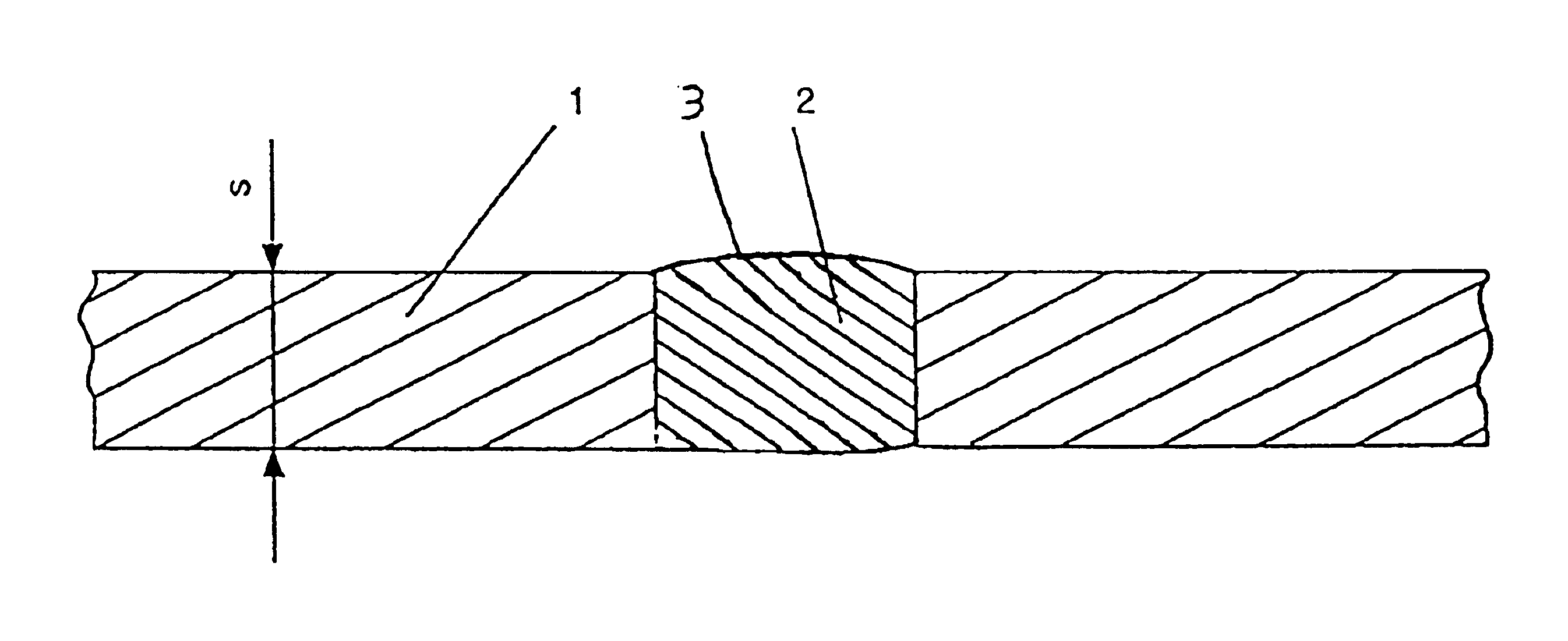
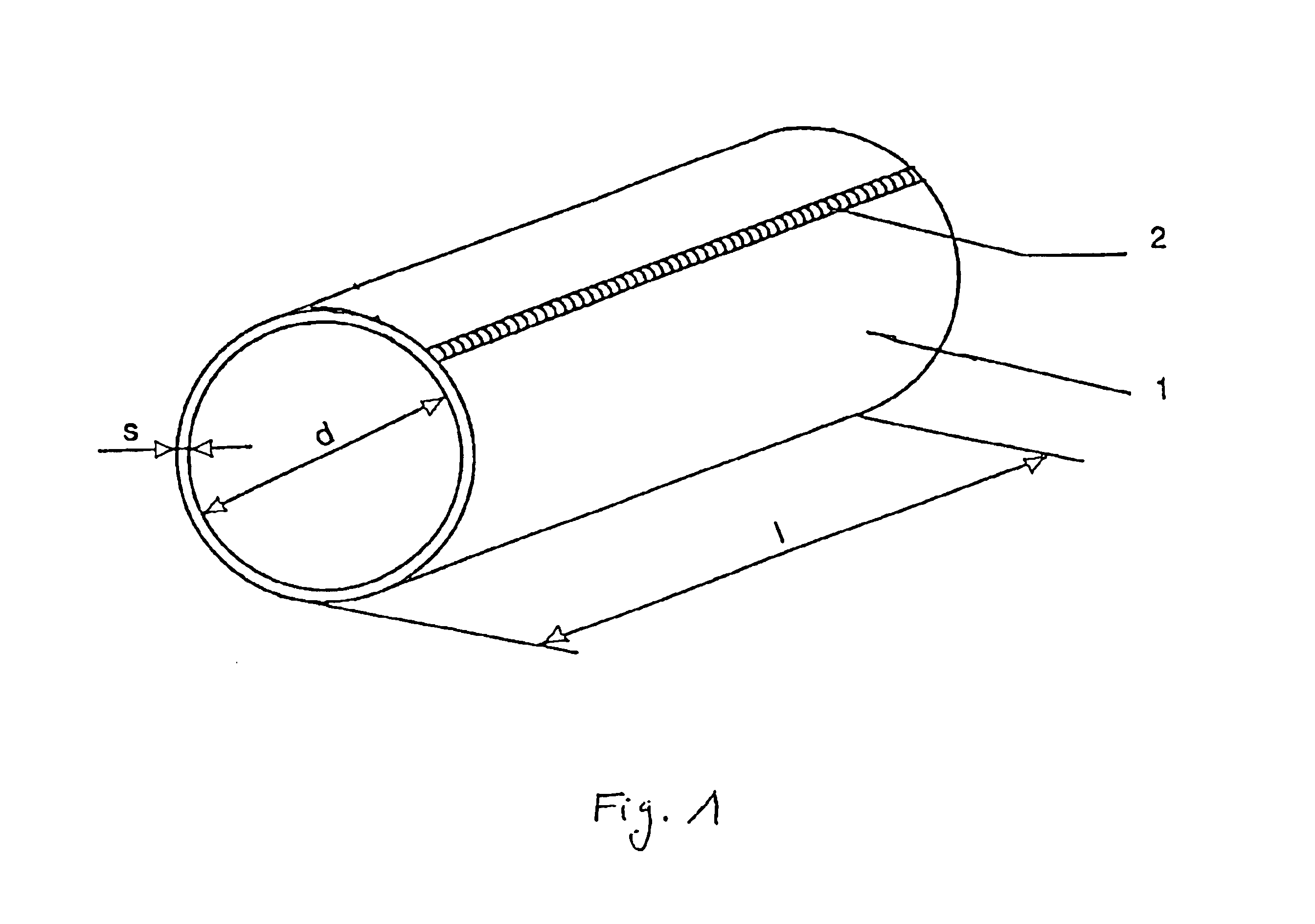
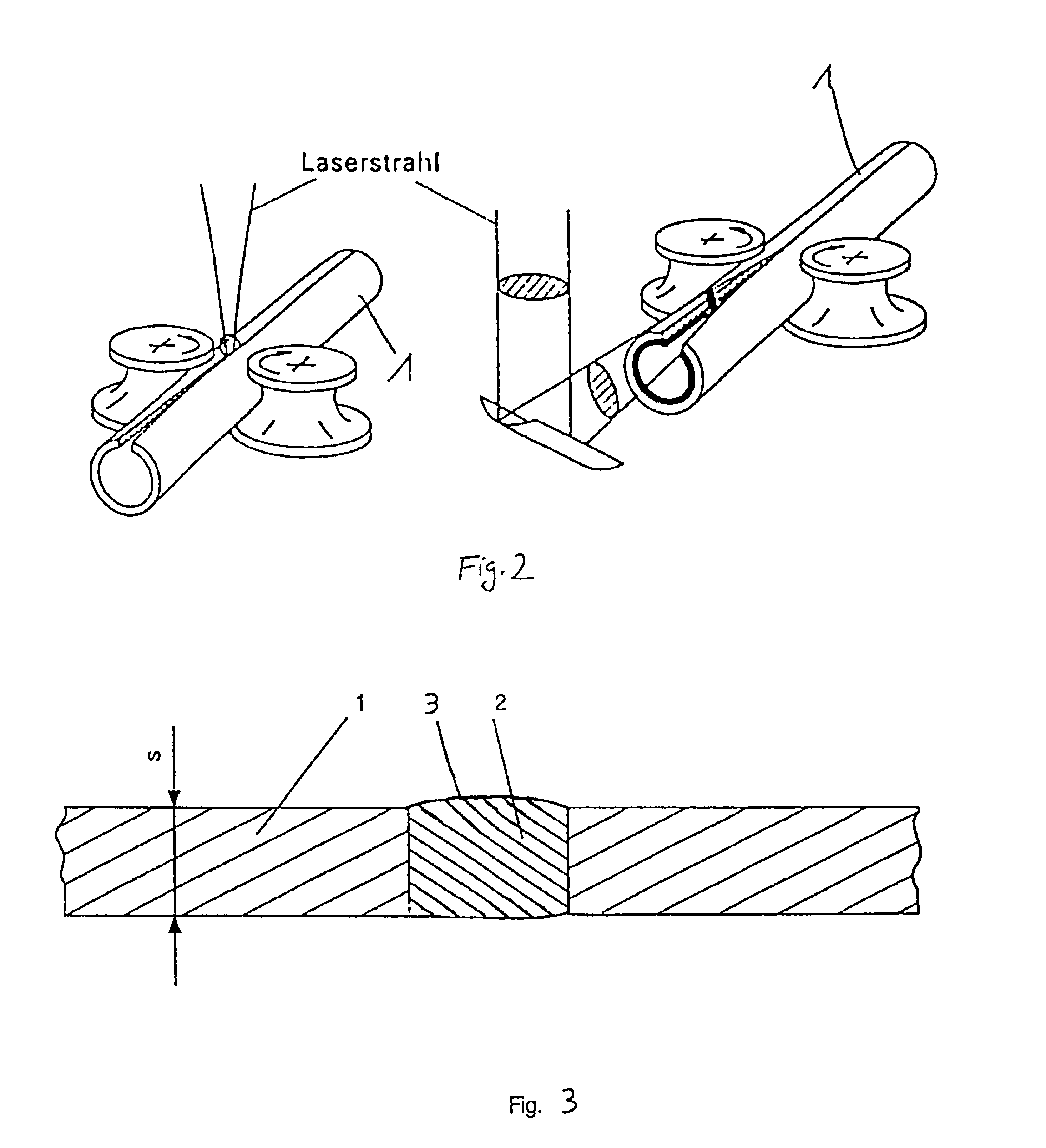
FIG. 1 shows, in highly schematic fashion, an example of a carrying sleeve 1 of a metal material, which may be aluminum, steel, high-quality steel or brass. The initial form is a rectangular, thin-walled flat sheet, which is bent into the desired hollow cylindrical form. Preferably, the edges of the flat sheet pointing toward one another are permanently connected to one another by means of a welded seam 2.

FIG. 2 shows possible ways of producing the carrying sleeve 1 in a quasi-continuous fashion, as is currently known by those in the tube welding art. The welding process itself is carried out by a laser beam.. The precision sheets of aluminum, steel, high-quality steel, copper or brass preferably have a wall thickness s of 0.1 to 0.6 mm. The carrying sleeves may also be produced by means of the welding device known from DE 43 11 078.

The external surface of the welded carrying sleeve 1 is then processed to create a homogeneous, continuous outer surface. To carry out this surface proc...


PUM


Abstract

A carrying sleeve, for painting and transfer forms of a metal material, the initial form of which is a rectangular thin-walled flat sheet. The sheet is bent into the desired hollow cylindrical form and the edges of the sheet which point toward one another are permanently connected together. The sleeve surface is processed in order to form a homogeneous continuous outer surface, so that continuous printing can be carried out.

Description

BACKGROUND OF THE INVENTION1. Field of the InventionThe invention relates to a metal carrying sleeve for printing and transfer forms. The initial form of the sleeve is a rectangular, thin-walled flat sheet, which is shaped by bending into the desired hollow cylindrical form, and the edges of the flat sheet which point toward one another are connected permanently together.2. Description of the Prior ArtIt is known today from flexographic printing to place sleeve-type printing and transfer forms on galvanically-produced nickel sleeves. Printing and transfer forms produced in this manner can be slipped by means of pressurized air over a printing cylinder core in the known manner and affixed thereto by shutting off the air supply. Carrying sleeves of fiberglass-reinforced plastic and even of carbon-fiber-reinforced plastic are also used for this purpose. However, it is relatively expensive to use materials such as nickel and fiberglass-reinforced plastic or even carbon-fiber-reinforced ...

Claims


Application Information

Patent Timeline
IPC IPC(8): B41N1/00B41N1/20
CPCB41N1/20
Inventor HOFFMANN, EDUARDPREM, WOLFGANGWINTERHOLLER, JOHANN
Owner MANROLANAD AG
Why Eureka
Try Eureka