Glare tester attachment

a technology of glare tester and attachment, which is applied in the field of glare tester, can solve the problems of not being indicative, not being able to recharge in a standard recharging mode, and visual acuity of patients

Inactive Publication Date: 2004-08-31
EPITROPOULOS ALICE T
View PDF2 Cites 13 Cited by
  • Summary
  • Abstract
  • Description
  • Claims
  • Application Information

AI Technical Summary

Benefits of technology

A further object is to provide a convenient and inexpensive glare tester.
A further object is to provide a glare tester that can be recharged in a standard ophthalmic recharging well.

Problems solved by technology

In recent years it has been discovered that the visual acuity of a patient measured in a standard dark refracting lane in an ophthalmologist's or optometrist's office may not be indicative of the patient's acuity in conditions of bright light or glare, especially where the patient suffers from eye disorders such as cataracts or corneal scars.
Current testers are marketed as separate instruments that require the use of a separate charging unit and are not capable of being recharged in a standard recharging well used for other examination instruments such as ophthalmoscopes, retinoscopes, and transilluminators.
Furthermore, even if a separate glare tester were compatible with standard recharging units, such units typically do not provide enough charging wells to accommodate a glare tester in addition to the conventional ophthalmic examination instruments.

Method used


Image

  • Glare tester attachment
  • Glare tester attachment
  • Glare tester attachment

Examples


Embodiment Construction

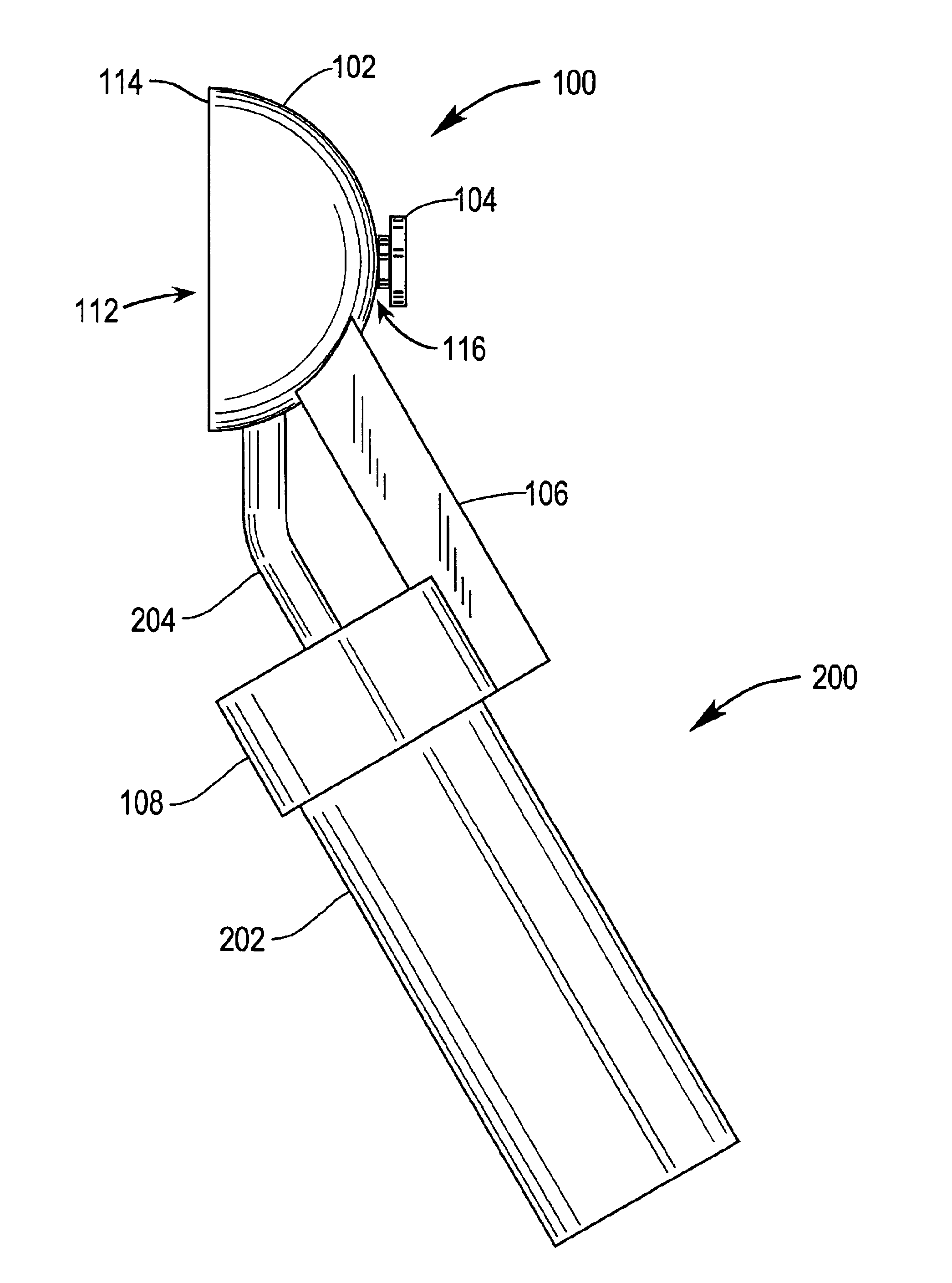
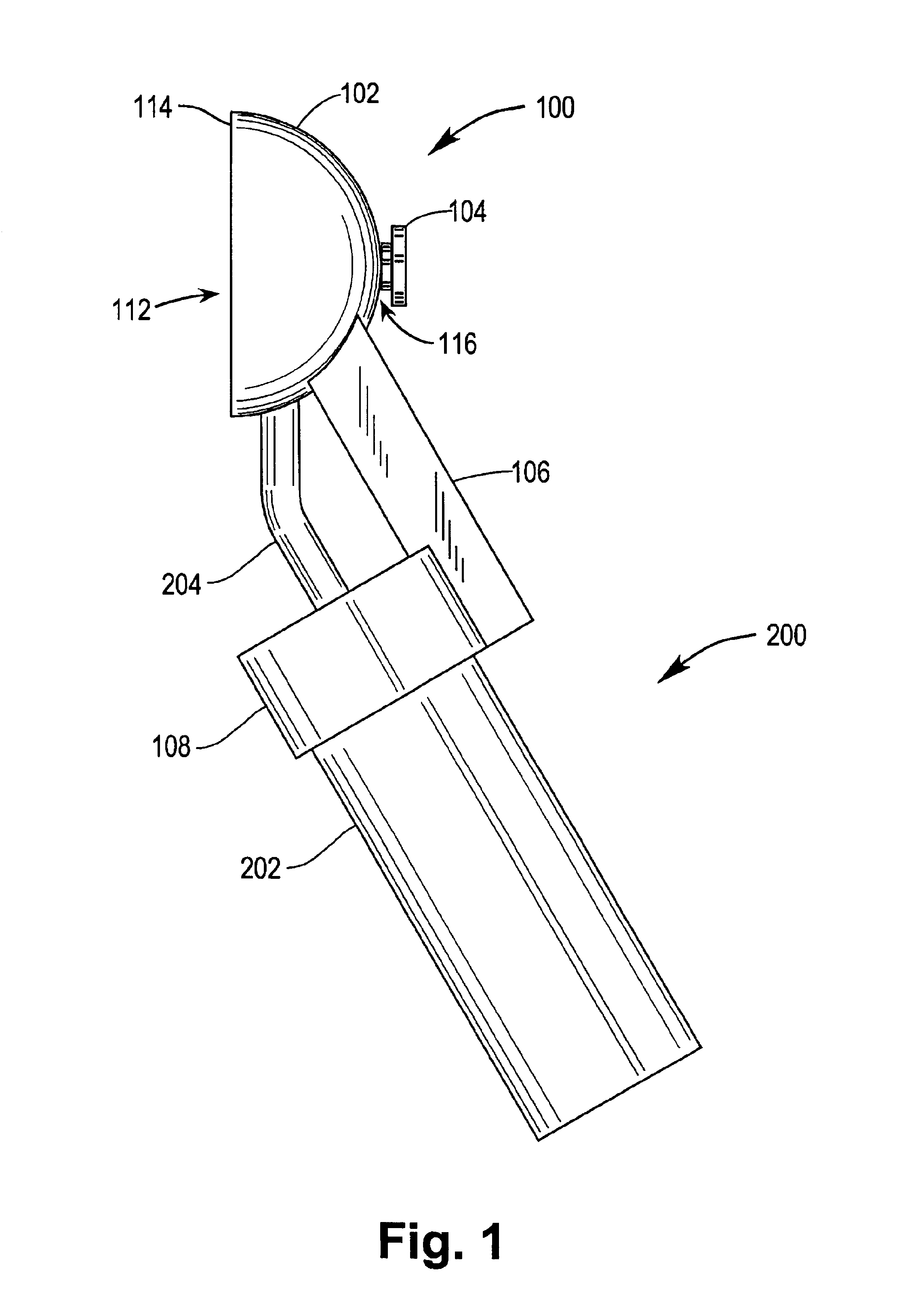
According to the invention a glare tester incorporates

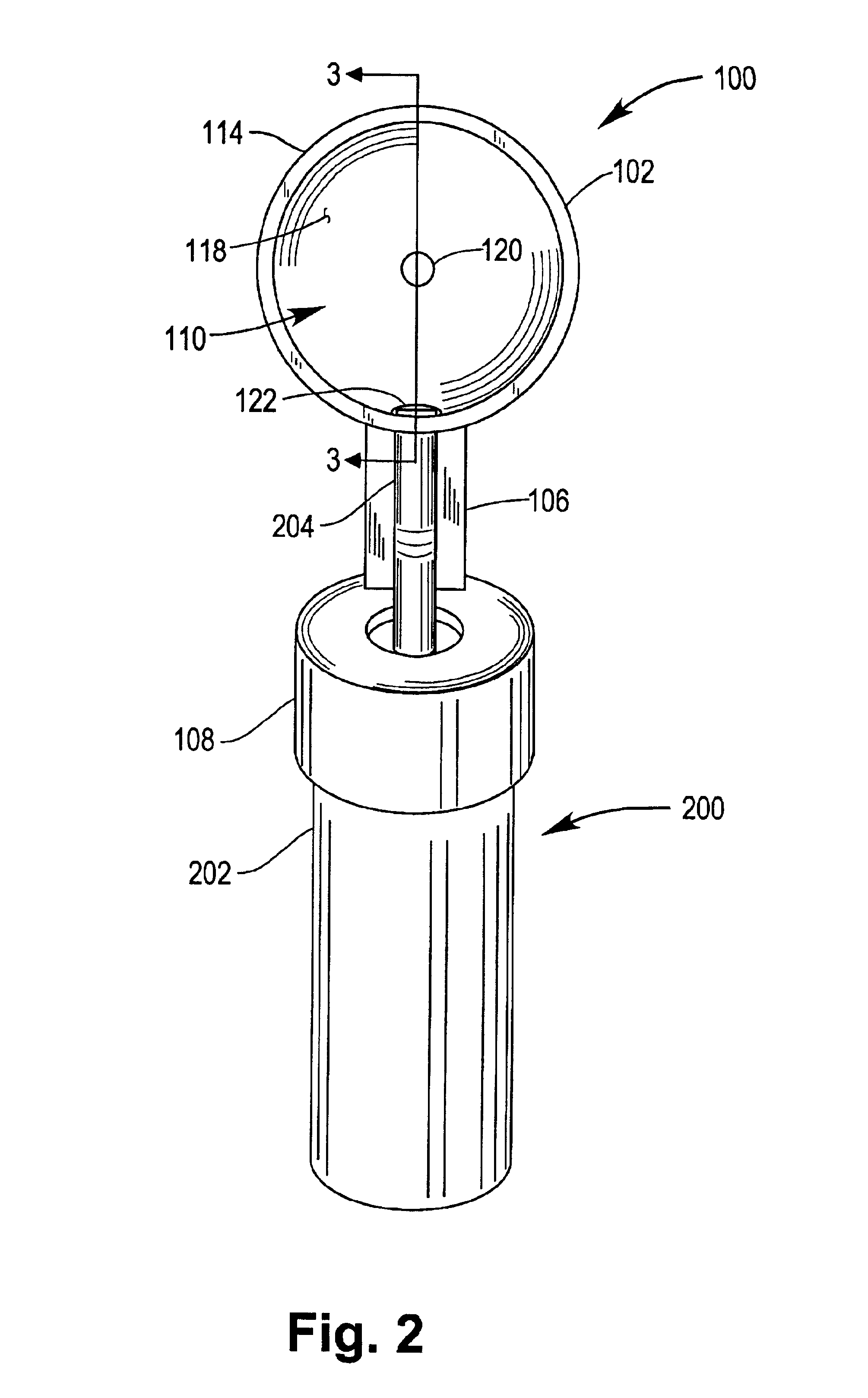
a generally concave reflector for providing diffuse illumination to an eye, the reflector comprising a wall having an interior light-reflecting surface at least partially enclosing a hollow interior chamber,

mounting means for removably supporting the reflector on a source of illumination; and

means for conducting illumination from the source of illumination to the interior light reflecting surface.

The concave reflector of the invention comprises a chamber having a wall partially surrounding a hollow interior. One side of the chamber has an opening generally sized to cover the orbit when placed in front of the eye. Accordingly, the orbital opening of the reflector is bounded by a rim, which may have any convenient shape. Thus the orbital opening of the reflector may be circular, elliptical, rectangular, or the like. A preferred shape for the orbital opening of the reflector is circular.

The depth of the illumination chamber defined ...


PUM


Abstract

An ophthalmic glare tester for evaluating visual acuity under conditions of strong diffuse illumination is designed for convenient mounting on a conventional ophthalmic instrument such as a transilluminator or ophthalmoscope. The glare tester incorporates a generally concave reflector for providing diffuse illumination to an eye and a mounting for attachment to an ophthalmic instrument. The reflector includes a wall having an interior light-reflecting surface at least partially enclosing a hollow interior. The glare tester provides for conducting illumination from the ophthalmic instrument to the interior light reflecting surface of the reflector.

Description

1. Field of the InventionThis invention relates to a glare tester and more specifically to a glare tester attachment suitable for use with a standard ophthalmic instrument.2. Brief Description of the Prior ArtIn recent years it has been discovered that the visual acuity of a patient measured in a standard dark refracting lane in an ophthalmologist's or optometrist's office may not be indicative of the patient's acuity in conditions of bright light or glare, especially where the patient suffers from eye disorders such as cataracts or corneal scars. In order to provide a more thorough assessment of a patient's visual acuity, brightness acuity or "glare" testers have been devised. One type of glare tester subjects the eye to be tested to a bright generally uniform illumination while the patient observes a test chart, e.g., a standard Snellen chart. This "brightness acuity test" provides an objective measurement of visual acuity under bright light conditions. It is useful to evaluate vi...

Claims


Application Information

Patent Timeline
Patent Type & Authority Patents(United States)
IPC IPC(8): A61B3/028A61B3/02
CPCA61B3/028A61B3/06
Inventor EPITROPOULOS, ALICE T.
Owner EPITROPOULOS ALICE T
Why Eureka
Try Eureka