Method, apparatus, and medium of digital acoustic signal coding long/short blocks judgement by frame difference of perceptual entropy

rame difference technology, applied in the field of digital acoustic signal coding apparatus, a method of coding a digital acoustic signal, and a recording medium, can solve the problems of 77% as to the upper limit, distortion of the signal generally, and limitation of the compression factor

Inactive Publication Date: 2004-09-28
RICOH KK
View PDF5 Cites 65 Cited by
  • Summary
  • Abstract
  • Description
  • Claims
  • Application Information

AI Technical Summary

Problems solved by technology

However, in the latter method, the distortion of the signal generally occurs.
However, there is a limitation as to the compression factor, e.g., almost 77% as to the upper limit.
Therefore, the technology of non-reversible compression is inevitably required.
However, the original signal value does not coincide with the restored value in general, and therefore an error occurs.
Such an error is called a "quantization error".
In such a way, in utilizing quantization, the original signal value cannot be completely restored.
However, the average quantization error is also increased.
The aforementioned quantization error results in the deterioration of sound quality in acoustic signal compression.
In the area of a small threshold value, if the number of quantization levels is not made large, the deterioration of sound quality may become prominent.
However, the aforementioned masking effect cannot be suitably applied to such a row as it is.
As a result, the small sound cannot be heard.
Therefore, if the intensity error of the original sound and the coded / decoded sound does not exceed the lower limit thereof, the difference between both of them cannot be sensed.
On the contrary, if the short blocks are applied to the signal as shown in FIG. 12, adequate bit allocation cannot be performed due to insufficient resolution in the frequency area.
As a result, a coding efficiency is lowered and noise occurs.
As to the short blocks, there further arises a problem of dividing (separating) these into groups.
If the dividing into groups is not performed suitably, that results in an increase of the code amount (number) and the lowering of the sound quality.
However, in the above long / short block judgment method, a suitable judgment is not always made.
Namely, the part that should be judged to be short is judged to be long (or vice versa) and thereby the sound quality is deteriorated on some occasions.
According to such a method, since the perceptual entropy is not considered by use of only the square sum of the input signal, the judgment coinciding with the audio property cannot always made.
Consequently, there is a possibility that the sound quality will deteriorate.
However, there exists a case of not being able to perform suitable judgment of long / short even in this method mentioned above.
As the result, the deterioration of the sound quality will be heard.
However, according to such background arts, for instance, and as disclosed in the background-art documents, e.g., the published specification of Japanese Laid-open Patent Publication No. 9-232964 and the other documents relating to MPEG-2 Audio AAC (Advanced Audio Coding) standardized in ISO / IEC 13818-7, MDCT (Modified Discrete Cosine Transform), and the M / S (MS stereo-Middle Side Stereo), etc., there exists no advantageous functional effect for improving the above-mentioned apparatus, method, and recording medium.
Even in the background-art methods mentioned above, the judgment of long / short is not performed suitably on all occasions.
On the other hand, when the threshold value with respect to the difference between the sums (sum values) of perceptual entropies of the respective short blocks takes a common value regardless of the sampling frequency, there arises a problem to be solved that, even though the long / short judgment can be suitably performed at a (certain) sampling frequency, the same judgment cannot be suitably performed at other sampling frequencies.

Method used


Image

  • Method, apparatus, and medium of digital acoustic signal coding long/short blocks judgement by frame difference of perceptual entropy
  • Method, apparatus, and medium of digital acoustic signal coding long/short blocks judgement by frame difference of perceptual entropy
  • Method, apparatus, and medium of digital acoustic signal coding long/short blocks judgement by frame difference of perceptual entropy

Examples


first embodiment

The first embodiment of the present invention is described hereinafter, referring to the accompanying drawings.

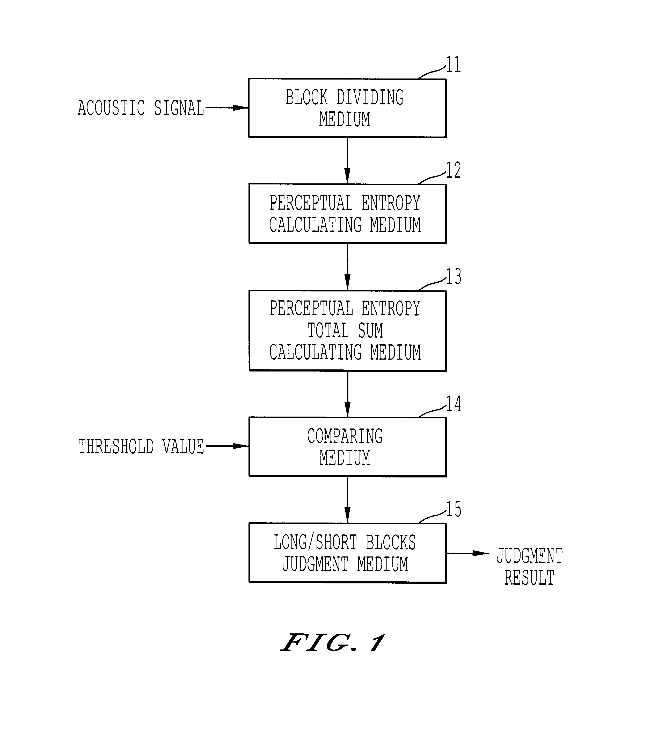
FIG. 1 is a block diagram illustrating the structure of a digital acoustic signal coding apparatus relating to the first embodiment of the invention. The digital acoustic signal coding apparatus of the embodiment as shown in FIG. 1 is constructed with a block dividing medium 11 for dividing the inputted acoustic signal into the predetermined number of blocks, e.g., eight successive blocks in the following explanation; a perceptual entropy calculating medium 12 for calculating the perceptual entropy PE of the respective divided blocks in accordance with the above-mentioned calculation formula; a perceptual entropy total sum calculating medium 13 for obtaining the total sum in the frame of the calculated perceptual entropy; a comparison medium 14 or comparing the absolute value of the difference between the respective total sums, in the frame, of the perceptual entropy of the...

second embodiment

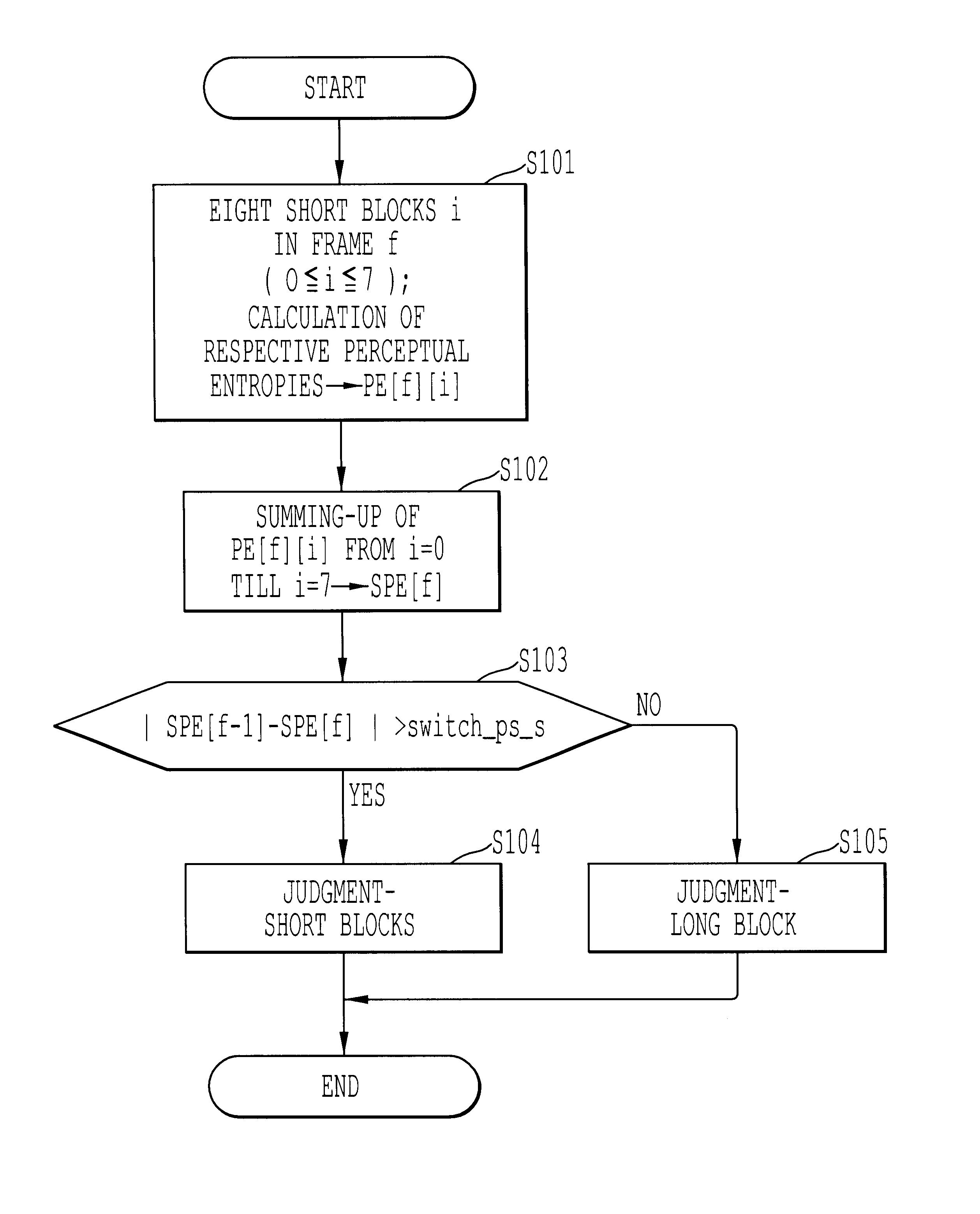
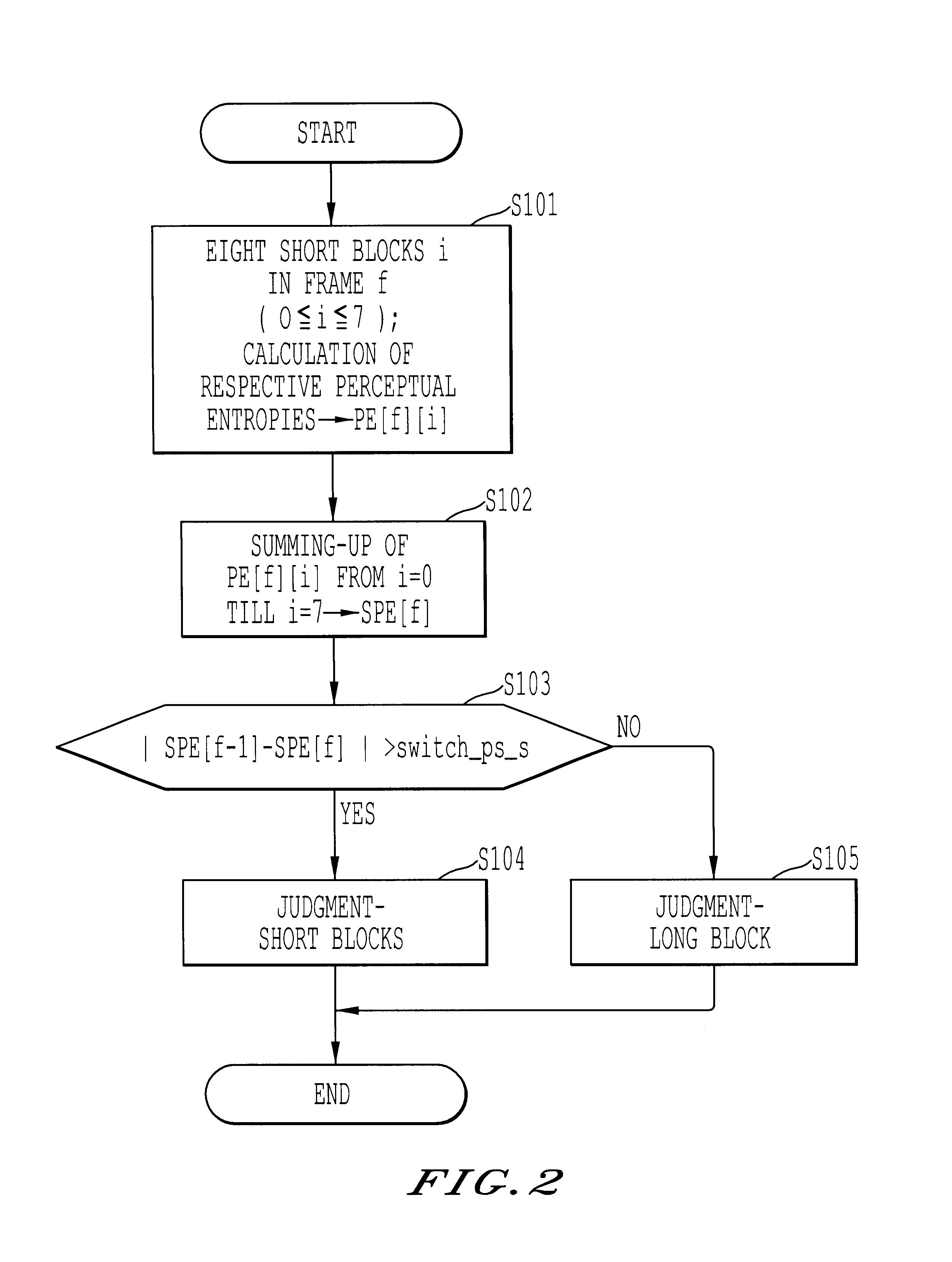
Next, the operation of the digital acoustic signal coding apparatus relating to the second embodiment according to the present invention is explained in accordance with the flow chart shown in FIG. 5. The processes associated with S101-S104 shown in FIG. 2 are the same in the respectively performed with respect to steps S201-S204 shown in FIG. 5. Only different operations are described here, and, thus, the description of these same operations is omitted here.

In step S203, the absolute value of the difference between the value SPE[f-1] which is already obtained at the previous frame f-1 in the same way as mentioned above and the value SPE[f] and the absolute value thus obtained is compared with the predetermined threshold value switch_pe_s. When the obtained absolute value is larger than switch_pe_s, the step advances to step S204 and the frame f is judged to be suitable for conversion with plural short blocks. On the other hand, when the obtained absolute value is smaller than switc...

third embodiment

Furthermore, although one of switch_pe_s is determined in FIG. 2 and FIG. 5, it is also allowable to previously determine the value per each of the sampling frequencies of the input acoustic signal as in the case of FIG. 7 showing the example of the value of switch_pe_s per each of the sampling frequencies, and set the value of switch_pe_s, referring to FIG. 7, in accordance with the sampling frequency of the acoustic signal inputted practically.

Next, the system structure of the present invention is illustrated in the block diagram of FIG. 8. Namely, FIG. 8 shows hardware constructed with a microprocessor controlled by software using digital acoustic signal coding methods of the above-mentioned embodiments. In FIG. 8, the digital acoustic signal coding system is constructed with an interface (hereinafter, abbreviated as I / F) 81, a CPU 82, a ROM 83, a RAM 84, A displaying apparatus 85, a hard disc 86, a keyboard 87, and a CD-ROM drive 88.

Furthermore, the commonly-used processing appa...


PUM


Abstract

A digital acoustic signal coding apparatus, a method of coding the digital acoustic signal, and a recording medium for recording a program of coding the digital acoustic signal are respectively realized. It is possible to provide the digital acoustic signal coding method and apparatus, in which, corresponding to the difference between the sampling frequencies of the input acoustic signal, short blocks can be suitably classified into groups without deteriorating sound quality and the suitability of using either long/short blocks can be judged. The coding apparatus is composed of a calculation medium for calculating the sensation entropy of an input acoustic signal per each of the respective short sensation blocks; a sensation entropy sum total calculation medium for obtaining a total sum in a frame of the sensation entropy; a comparison medium for comparing an absolute value of the difference between the respective total sums of the sensation entropy of successive two frames with a previously determined threshold value; and a long/short block judgment medium for judging whether a long block or short blocks should be used to convert a block of the input acoustic signal on the basis of the comparison result.

Description

1. Field of the InventionThe present invention relates to a digital acoustic signal coding apparatus, a method of coding a digital acoustic signal, and a recording medium for recording a program of coding the digital acoustic signal, in particular, the compression / coding of a digital acoustic signal utilized in, for instance, DVD recording / reproducing or in a digital broadcast, etc.2. Discussion of the BackgroundThe background arts are discussed with the main focus being on the compression of an acoustic signal.At present, in the digital audio field, MP3 is a very popular coding technique MP3 is an abbreviation for an acoustic signal compression coding method called "MPEG-1 Audio Layer III". By employing MP3, digital audio such as data used for a CD, can be compressed to the extent of 1 / 11 without deteriorating the sound quality. Because of the convenience of compressing a large volume of acoustic data to a compact size that can be transmitted in a short time, MP3 is becoming popula...

Claims


Application Information

Patent Timeline
Patent Type & Authority Patents(United States)
IPC IPC(8): G10L19/00G10L19/02G10L19/025H03M7/30
CPCG10L19/0208G10L19/02
Inventor ARAKI, TADASHI
Owner RICOH KK
Why Eureka
Try Eureka