Aircraft control surface drive system and associated methods

a technology for controlling surfaces and aircraft, applied in the direction of aircrafts, power amplifiers, transportation and packaging, etc., can solve the problems heavy and costly conventional drive systems, and high cost, and achieve the effect of reducing the cost of hydraulic flap drive systems

Inactive Publication Date: 2004-10-05
THE BOEING CO
View PDF21 Cites 81 Cited by
  • Summary
  • Abstract
  • Description
  • Claims
  • Application Information

AI Technical Summary

Benefits of technology

Aspects of embodiments of the invention are directed to drive systems for aircraft control surfaces, such as trailing edge flaps and leading edge slats. One embodiment provides an actuator control system for controlling first and second control portions. The system comprises first and second supply lines and a return line coupleable to a source of fluid. A fluid-driven actuator is connected to at least one of the first and second control portions. The fluid-driven actuator is in fluid communication with the first and second supply lines. A flow control assembly is connected to the first supply line and to the return line. The flow control is configured to control the flow of fluid in one direction from the first supply line to the fluid-driven actuators and to control the flow of fluid in another direction from the fluid-driven actuator to the return line. A bypass line is in fluid communication with the first and second supply lines and is positioned to provide fluid from the second supply line into the first supply line at a position intermediate the source and the fluid-driven actuator.
Another embodiment provides an aircraft system having first and second control surfaces, a source of hydraulic fluid, a first control system coupled to the first control surface, and a second control system coupled to the second control surface. Each of the first and second control systems comprises first and second supply lines coupled to the source of hydraulic fluid, and a return line coupled to the source of hydraulic fluid. A hydraulic actuator is connected to at least one of the first and second aircraft control surfaces. The hydraulic actuator is movable between first and second positions, and is configured to receive hydraulic fluid from the first supply line when the hydraulic actuator moves toward the first position. The hydraulic actuator is also configured to receive hydraulic fluid from the second supply line when the hydraulic actuato

Problems solved by technology

These conventional drive systems, however, can be very heavy and costly.
The resulting hydraulic flap d

Method used


Image

  • Aircraft control surface drive system and associated methods
  • Aircraft control surface drive system and associated methods
  • Aircraft control surface drive system and associated methods

Examples


Embodiment Construction

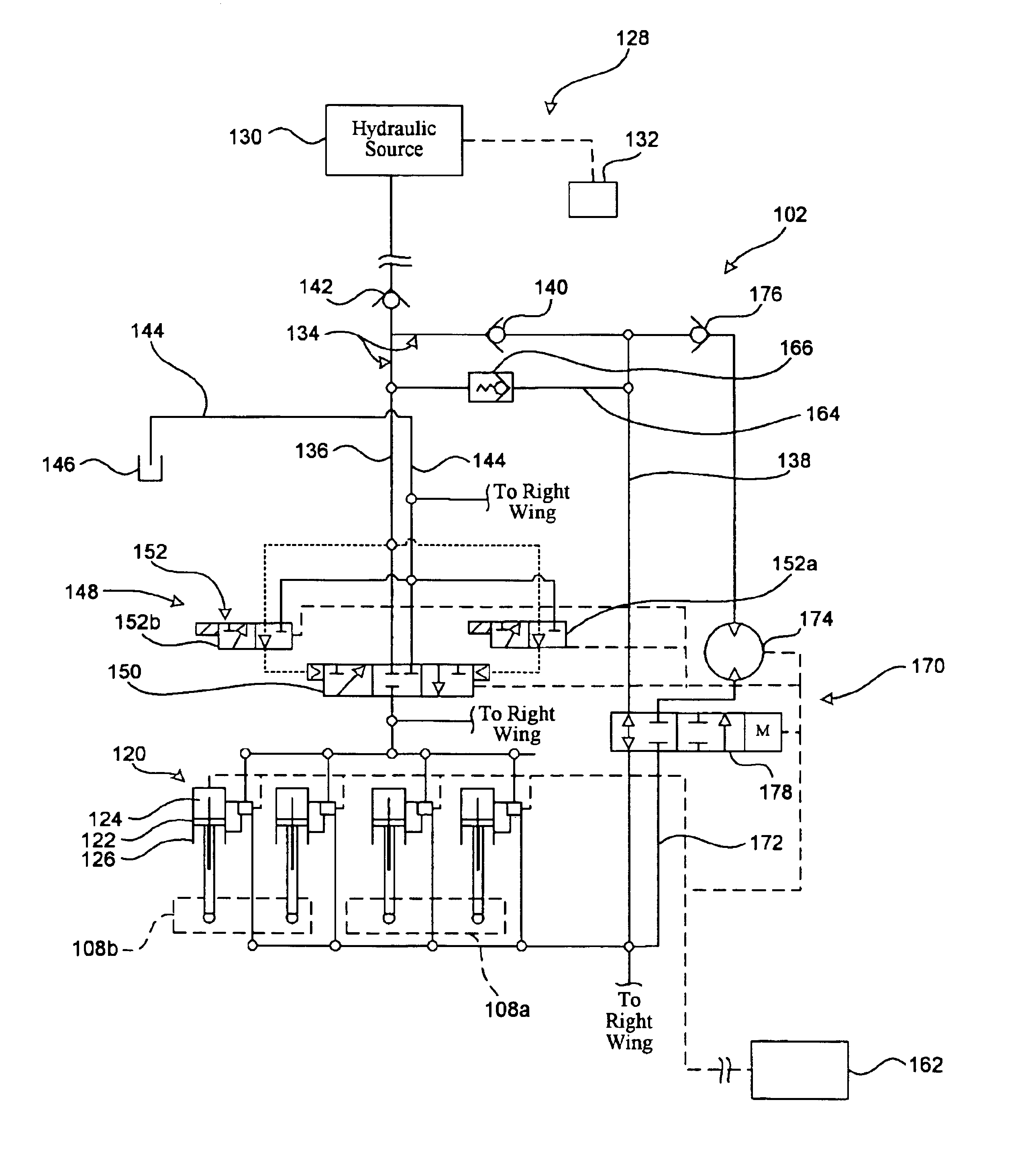
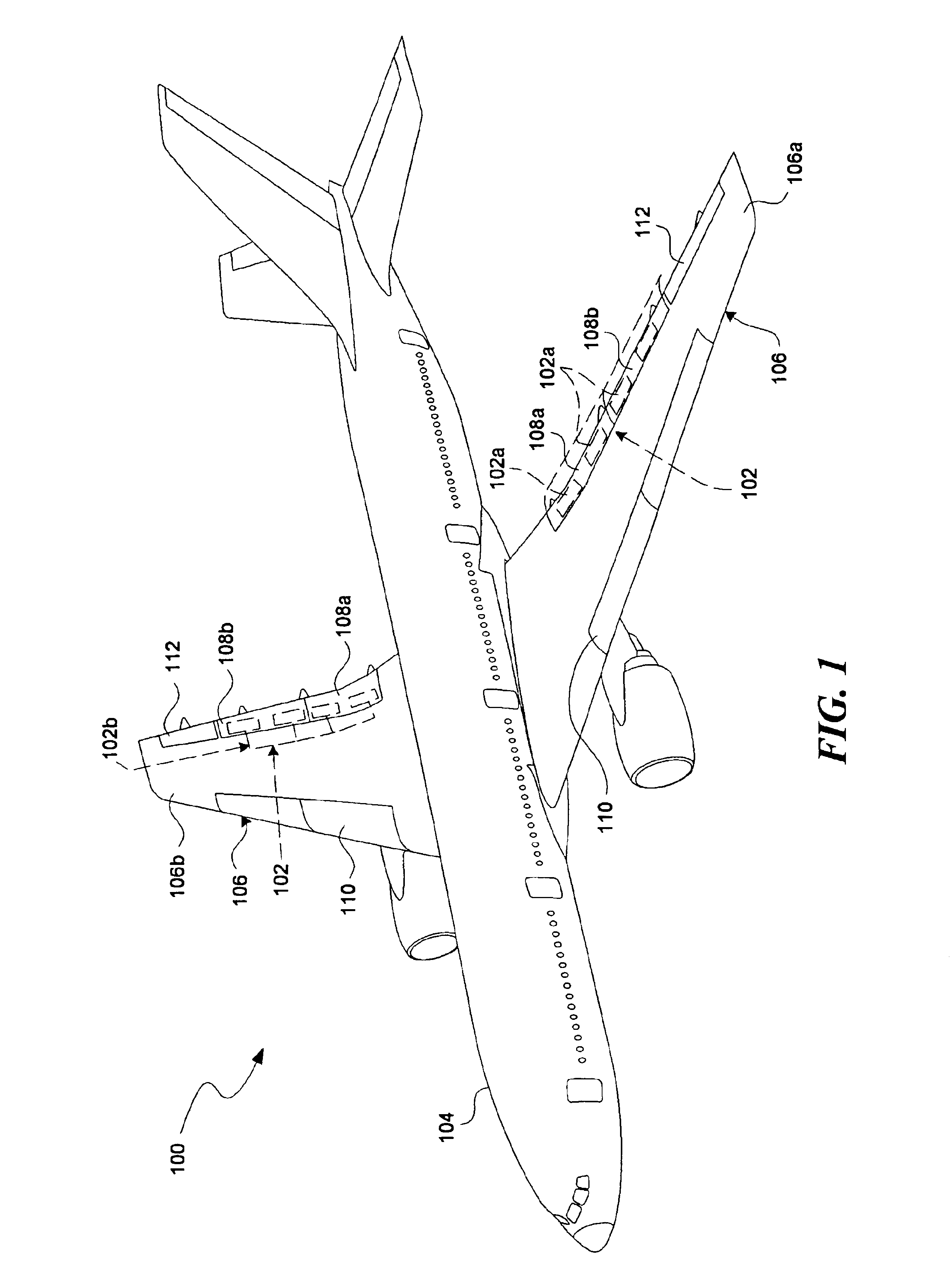
The following disclosure describes drive systems for use with aircraft trailing edge flaps and other aircraft control surfaces. Certain specific details are set forth in the following description and in FIGS. 1-4 to provide a thorough understanding of various embodiments of the invention. Other details describing the well-known structures and systems often associated with aircraft, and more specifically with aircraft control surface drive systems, are not set forth in the following description to avoid unnecessarily obscuring the description of the various embodiments of the invention.

Many of the details, dimensions, and other specifications shown in the Figures are merely illustrative of particular embodiments of the invention. Accordingly, other embodiments can have other details, dimensions, and specifications without departing from the spirit or scope of the present invention. In addition, other embodiments of the invention may be practiced without several of the details describ...


PUM

PropertyMeasurementUnit
Flow rateaaaaaaaaaa

Abstract

A control surface drive system having a plurality of actuator assemblies are coupled to first and second supply lines and to a return line. The first and second supply lines are connected to a source of hydraulic fluid. At least one of the actuator assemblies has a hydraulic actuator movably connectable to an aircraft control surface. A flow control assembly is connected to the return line and to at least one of the first and second supply lines. A bypass line is in fluid communication with the first and second supply lines and positioned to recycle the hydraulic fluid from one of the first and second supply lines back into the other one of the first and second supply lines when the hydraulic actuator moves toward the first position. A computer controller operatively interconnects the plurality of actuator assemblies and the flow control assembly. It is emphasized that this abstract is provided to comply with the rules requiring an abstract. It is submitted with the understanding that it will not be used to interpret or limit the scope or meaning of the claims (37 C.F.R..sctn.1.72(b)).

Description

TECHNICAL FIELDThis disclosure relates generally to drive systems for aircraft control surfaces, and more particularly to hydraulic drive systems for moving and controlling the aircraft control surfaces.BACKGROUNDAll aircraft include movable control surfaces for directional control in flight. Such control surfaces can include ailerons for roll control, elevators for pitch control, and rudders for yaw control. In addition, most conventional jet transport aircraft typically include leading edge slats and trailing edge flaps on the wings. These devices can be used to generate high lift during takeoff and landing when the aircraft is traveling at relatively low air speeds.Federal aviation regulations (FARS) impose airworthiness standards on lift and drag devices for transport category aircraft. For example, FAR .sctn.25.697 requires that such devices (e.g., trailing edge flaps) must maintain selected positions (e.g., extended positions) without further attention by the pilot. This requi...

Claims


Application Information

Patent Timeline
IPC IPC(8): B64C13/00B64C13/40B64D45/00
CPCB64C13/40B64D45/0005Y10T29/4933Y02T50/44B64D2045/001B64C13/42Y02T50/40Y10T137/87161
Inventor JONES, KELLY T.
Owner THE BOEING CO
Why Eureka
Try Eureka