Apparatus and method of detecting interfaces between well fluids

a technology of interface detection and fluid detection, applied in the field of apparatus and method, can solve the problems of increasing cost, increasing cost, and time-consuming conventional circulating cementing process, and increasing cos

Inactive Publication Date: 2004-10-12
BJ SERVICES LLC
View PDF24 Cites 93 Cited by
  • Summary
  • Abstract
  • Description
  • Claims
  • Application Information

AI Technical Summary

Problems solved by technology

The conventional circulating cementing process may be time-consuming, and thus relatively expensive, as cement must be pumped all the way to the bottom of the casing and then back up into the annulus.
Further, expensive chemical additives, such as curing retarders and cement fluid-loss control additives, are typically used, again increasing the cost.
This again increases cost.
Finally, present methods of determining when the slurry leaves the lower end of the casing generally require attention and action from the personnel located at the surface and may be inaccurate in some applications.
For instance, if the plug were to encounter debris in the casing and became lodged in the casing, personnel at the surface could incorrectly conclude the cement had left the lower end of the casing and job was completed.
However, this system only verifies that the plug has entered the casing, not that the plug has reached the bottom.
However, utilizing the reverse circulating cementing operation presents its own operational challenges.
For instance, since the cement slurry is pumped directly into the annulus from the surface, no conventional wiper plug can be used to help displace or push the cement down the annulus.
Further, unlike the conventional circulating cementing process where the inner diameter of the casing is known, the inner diameter of the wellbore is not known with precision, since the hole is typically washed out (i.e. enlarged) at various locations.
With this variance of the inner diameter of the wellbore, one cannot precisely calculate the volume of cement to reach the bottom of the casing, even when using open hole caliper logs.
Again, erroneous results may be produced from this system.
Also problematic is that fact that once any object is inserted into the casing, or annulus for that matter, its precise location of that object is no longer known with certainty.
For instance, in the conventional circulation cement process, if mud continues to be pumped into the casing after the mud / cement interface reaches the lower end of the casing, mud will enter the annulus thus contaminating the cement and jeopardizing the effectiveness of the cement job.
Similarly, in the reverse circulating cementing process, if cement--or displacement fluids--continue to be pumped from the surface once the mud / cement interface reaches the lower end of the casing, excessive cement will enter the interior of the casing.

Method used


Image

  • Apparatus and method of detecting interfaces between well fluids
  • Apparatus and method of detecting interfaces between well fluids
  • Apparatus and method of detecting interfaces between well fluids

Examples


Embodiment Construction

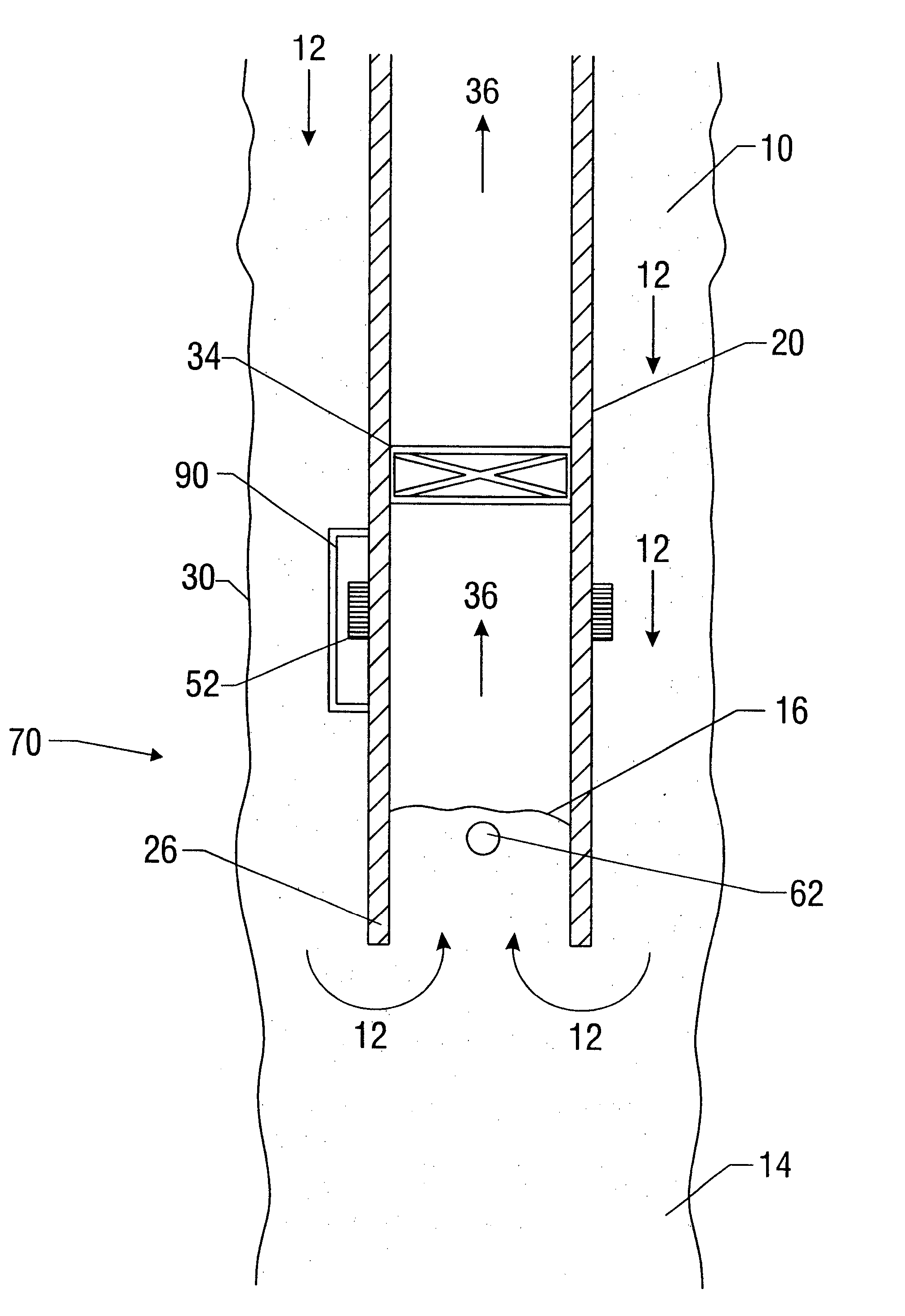
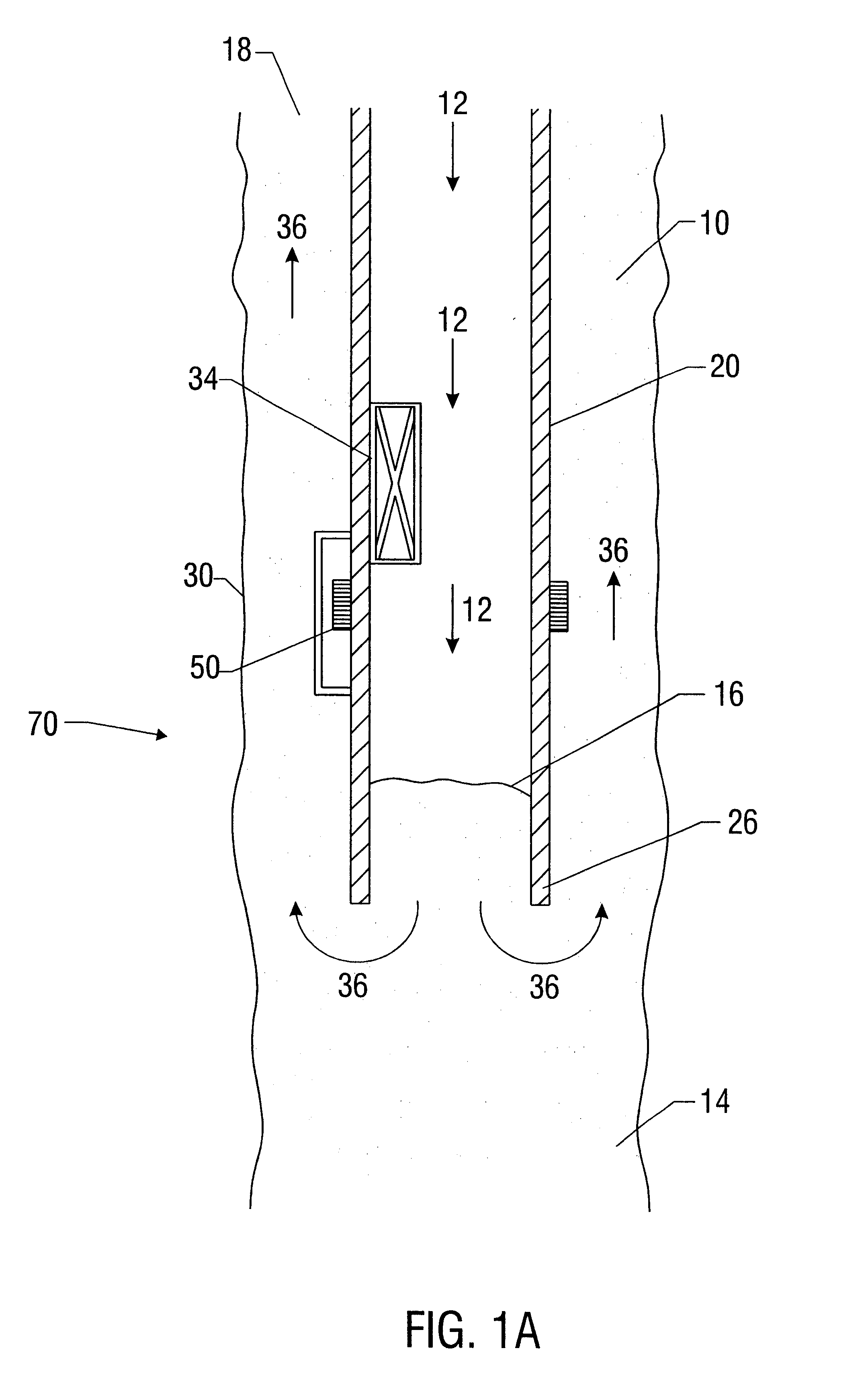
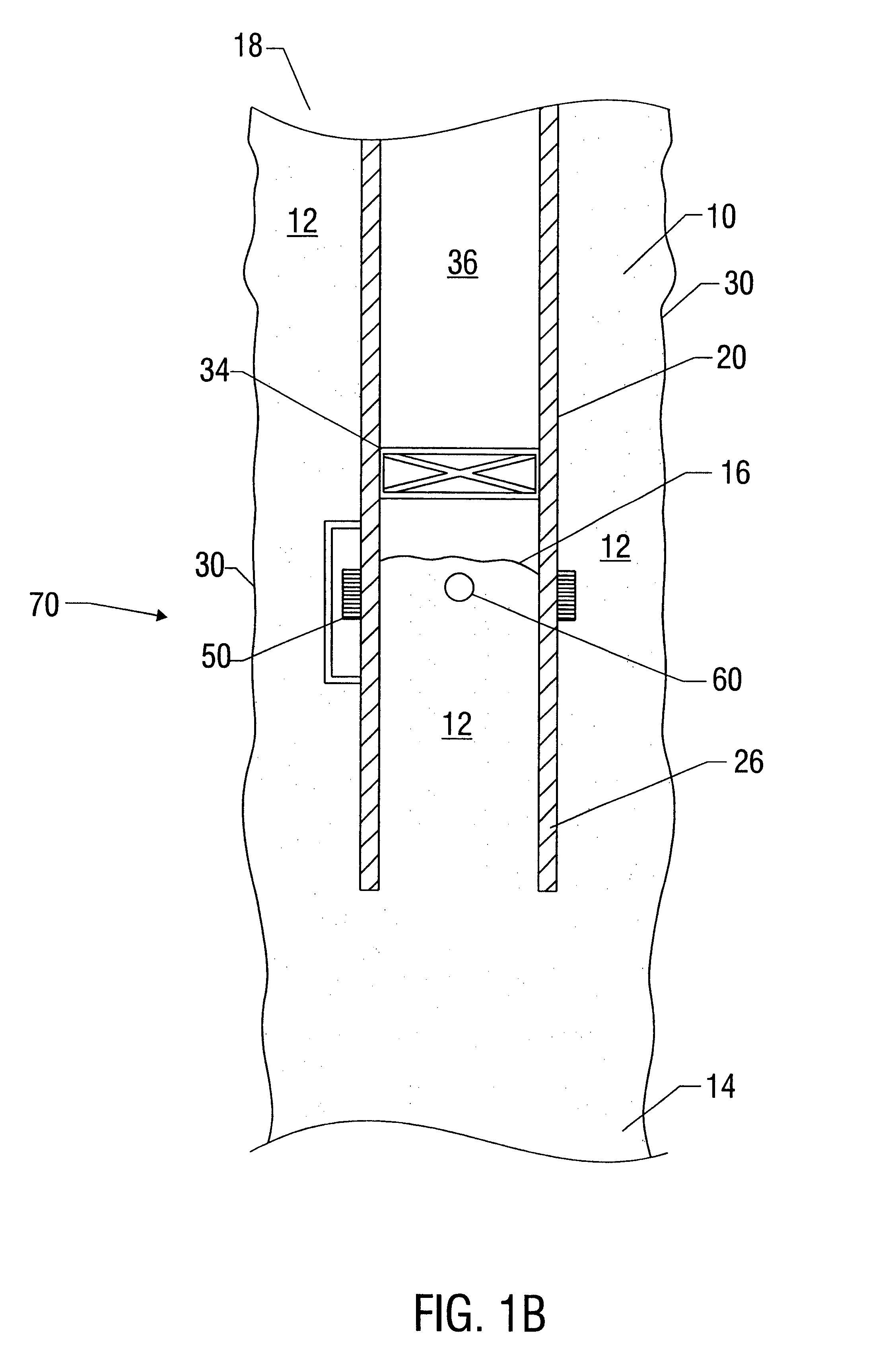
Illustrative embodiments of the invention are described below as they might be employed in the oil and gas recovery operation. In the interest of clarity, not all features of an actual implementation are described in this specification. It will of course be appreciated that in the development of any such actual embodiment, numerous implementation-specific decisions must be made to achieve the developers' specific goals which will vary from one implementation to another. Moreover, it will be appreciated that such a development effort might be complex and time-consuming, but would nevertheless be a routine undertaking for those of ordinary skill in the art having the benefit of this disclosure. Further aspects and advantages of the various embodiments of the invention will become apparent from consideration of the following description and drawings.

Embodiments of the invention will now be described with reference to the accompanying figures. Referring to FIGS. 1A and 1B, one embodimen...


PUM


Abstract

An apparatus for use in circulating cement in a casing in a wellbore is described having a first component such as a sensor disposed on the casing and a second component such as a detectable device disposed at a fluid interface formed between the cement and a fluid. The sensor may be a sensor coil mounted on the perimeter of the lower end of the casing, while the detectable device may be a transponder capable of emitting Radio Frequency Identification signals to the sensor to signal its arrival at the lower end of the casing. The transponder may be encased in a protective covering. Also described is a method of cementing a casing utilizing a first component such as a sensor disposed on the casing and a second component such as a detectable device disposed in the cement.

Description

1. Field of the InventionThe invention relates to an apparatus and method for use in the field of oil and gas recovery. More particularly, this invention relates to an apparatus having a first component such as a sensor and a second component such as a detectable device or material adapted to determine when a general interface region between two dissimilar fluids has passed a given point in a well.2. Description of the Related ArtCementing a wellbore is a common operation in the field of oil and gas recovery. Generally, once a wellbore has been drilled, a casing is inserted and cemented into the wellbore to seal off the annulus of the well and prevent the infiltration of water, among other things. A cement slurry is pumped down the casing and back up into the space or annulus between the casing and the wall of the wellbore. Once set, the cement slurry prevents fluid exchange between or among formation layers through which the wellbore passes and prevents gas from rising up the wellb...

Claims


Application Information

Patent Timeline
Patent Type & Authority Patents(United States)
IPC IPC(8): E21B33/138E21B33/03E21B33/05E21B47/00E21B47/09
CPCE21B33/05E21B47/09E21B33/138
Inventor DILLENBECK, ROBERT LEECARLSON, BRADLEY T.
Owner BJ SERVICES LLC
Why Eureka
Try Eureka