Aircraft service pit latch

a technology for aircraft and latches, applied in the direction of liquid materials, transportation and packaging, packaging goods types, etc., can solve the problems of difficult to clean out the dirt and other loading apron and runway debris that collect in order to free the lever arm of the latch mechanism

Inactive Publication Date: 2004-11-02
CAVOTEC ACQUISITION US
View PDF51 Cites 44 Cited by
  • Summary
  • Abstract
  • Description
  • Claims
  • Application Information

AI Technical Summary

Problems solved by technology

One difficulty with conventional latch mechanisms of this type that has persisted throughout the years is that the gap that provides access to the pit latch lever arm and the cavity in which the lever arm is mounted often becomes clogged with dirt and debris so that the user must first clean out these areas in order to free the pit lid latch lever arm so that it may be moved.
Since the gap at the edge of the pit lid is located below grade and the cavity in which the pit latch lever arm is located lies underneath the edge of the pit lid, it is often quite difficult to clean out the dirt and other loading apron and runway debris that collects in order to free the lever arm of the latch mechanism.

Method used


Image

  • Aircraft service pit latch
  • Aircraft service pit latch
  • Aircraft service pit latch

Examples


Embodiment Construction

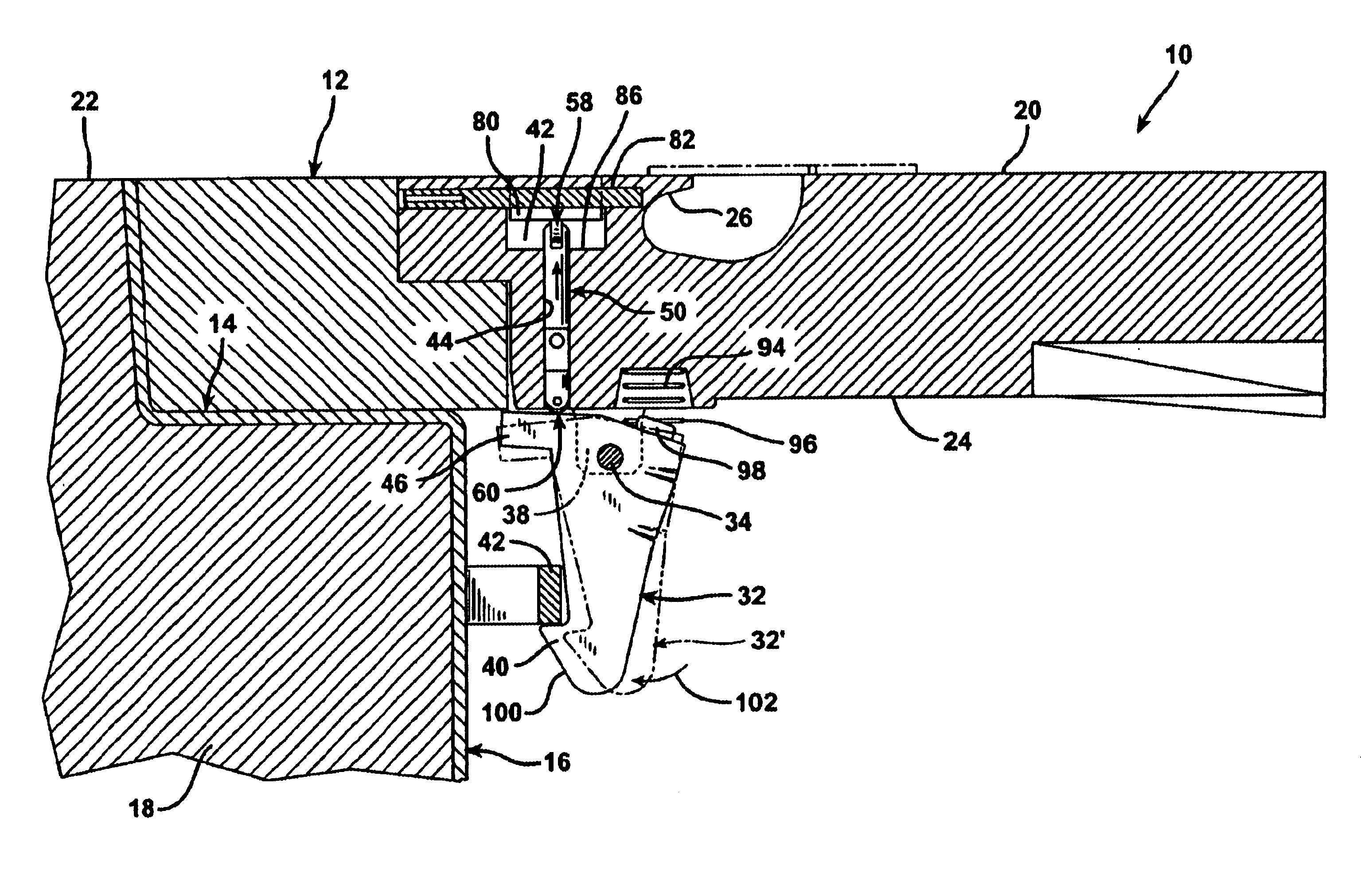
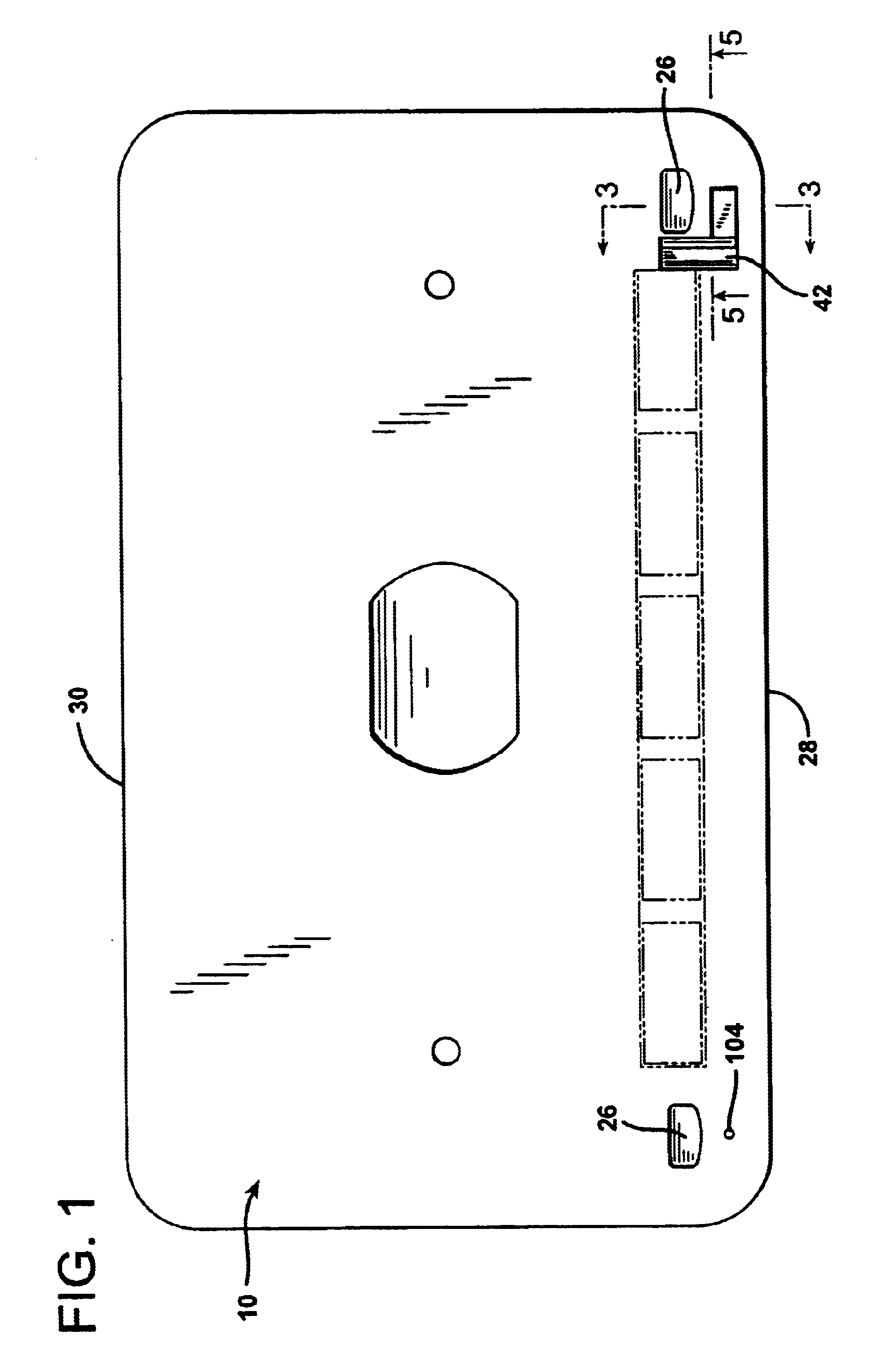
FIG. 1 illustrates stainless-steel prefabricated aircraft service pit lid 10 which is set into a surrounding frame 12, visible in FIG. 3. The pit lid 10 has a generally rectangular configuration, rounded at its corners. The pit frame 12 is seated atop a peripheral bearing ledge portion 14 formed at the upper extremity of a prefabricated fiberglass aircraft service pit 16. The aircraft service pit 16 is buried in the ground 18 so that the upper surface 20 of the pit lid 10 is flush with the upper surface of the surrounding frame 12 and with the surrounding surface 22 of the tarmac above the ground 18 in which it is buried.

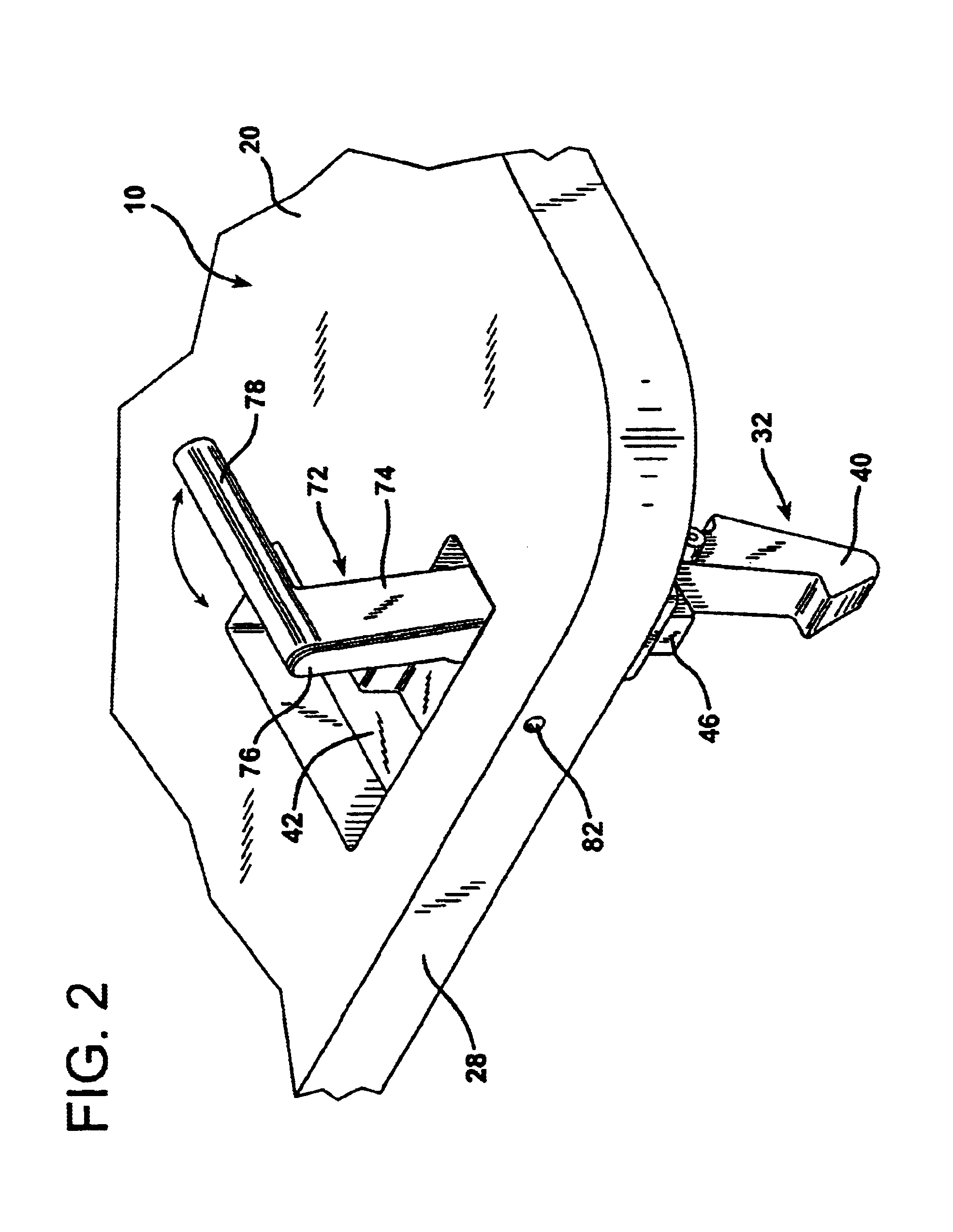
The undersurface 24 of the pit lid 10 is generally parallel to the upper surface 20 and lies in a substantially horizontal orientation when the pit lid 10 is seated in the frame 12, as illustrated in FIG. 3. Concave, scooped out conventional handgrips 26 are defined near the corners of the pit lid 10 proximate the free, unhinged edge 28 which lies opposite the hinge...


PUM

PropertyMeasurementUnit
angleaaaaaaaaaa
axes of rotationaaaaaaaaaa
angleaaaaaaaaaa

Abstract

A buried subsurface pit for use beneath a surface across which aircraft travel for servicing aircraft is provided with a pit latching mechanism for holding and releasing a pit lid mounted atop the buried pit. A shallow latch operating lever storage recess is defined in the upper surface of the pit lid. An actuator rod passageway is formed in the pit lid and extends between the latch operating lever storage recess and the undersurface of the pit lid. A catch is located in alignment with the actuator rod passageway at the undersurface of the pit lid. The catch is mounted for rotation about a horizontal axis of catch rotation. An actuator rod is disposed for longitudinal, reciprocal movement in the actuator rod passageway. A latch operating lever has opposing latch handle and actuator rod engaging ends. The latch operating lever is mounted between its opposing ends to the pit lid proximate the upper surface of the pit lid for rotation on a fulcrum about a horizontal latch operating lever axis of rotation which is located just below the upper surface of the pit lid. The latch operating lever is movable between a stored position in the latch operating lever storage recess and an actuator rod engaging position in which the latch handle end of the latch operating lever is raised out of the latch operating lever storage recess so that the actuator rod operating end of the lever depresses the actuator rod to disengage the catch.

Description

1. Field of the InventionThe present invention related to a latching or fastening mechanism for an access lid to a subsurface chamber for servicing aircraft.2. Description of the Prior ArtAt modern aircraft terminals the servicing of aircraft on the ground is frequently performed using subsurface pits, which are often prefabricated structures. Such aircraft servicing pits are installed at aircraft docking, fueling, and loading areas beneath the surface of the tarmac across which aircraft travel during docking and departure maneuvers. The pits form a subsurface chamber and are typically constructed of fiberglass, steel, concrete, or aluminum. These pits are often constructed as complete enclosures with surrounding walls, a floor, and an access lid at the top seated within a frame disposed about the neck of the prefabricated pit. When the lid is closed it lies substantially flush with the surface of the tarmac. Such pits are installed below the surface of loading and refueling aprons ...

Claims


Application Information

Patent Timeline
Patent Type & Authority Patents(United States)
IPC IPC(8): E02D29/14E05B65/00
CPCE05B65/006E02D29/1427Y10T292/0929
Inventor PETERSEN, CRAIGHERNANDEZ, DENNIS
Owner CAVOTEC ACQUISITION US
Why Eureka
Try Eureka