Lens apparatus and image-taking apparatus

a technology of image-taking apparatus and lens, which is applied in the field of barrel mounting, can solve the problems of impaired design freedom and impaired design freedom, and achieve the effect of improving the degree of design freedom

Inactive Publication Date: 2004-11-23
CANON KK
View PDF13 Cites 19 Cited by
  • Summary
  • Abstract
  • Description
  • Claims
  • Application Information

AI Technical Summary

Benefits of technology

It is an object of the present invention to provide a lens apparatus which is easy to assemble and at the same time which achieves a high degree of design freedom while securing sufficient strength at the flange portion.

Problems solved by technology

However, if it is mandatory to arrange the protruded portion 101b at the position of the phase same as that of opening portion 101c, the degree of design freedom is impaired.
This may impair the degree of design freedom.

Method used


Image

  • Lens apparatus and image-taking apparatus
  • Lens apparatus and image-taking apparatus
  • Lens apparatus and image-taking apparatus

Examples


Embodiment Construction

Referring now to drawings, embodiments of the present invention will be described in detail as follows.

First of all, FIG. 5 is an external view of a camera equipped with a lens barrel according to the present embodiment. In FIG. 5, numeral 60 denotes a camera body, and at the front center of this camera body 60, a lens barrel 61 which can zoom is placed.

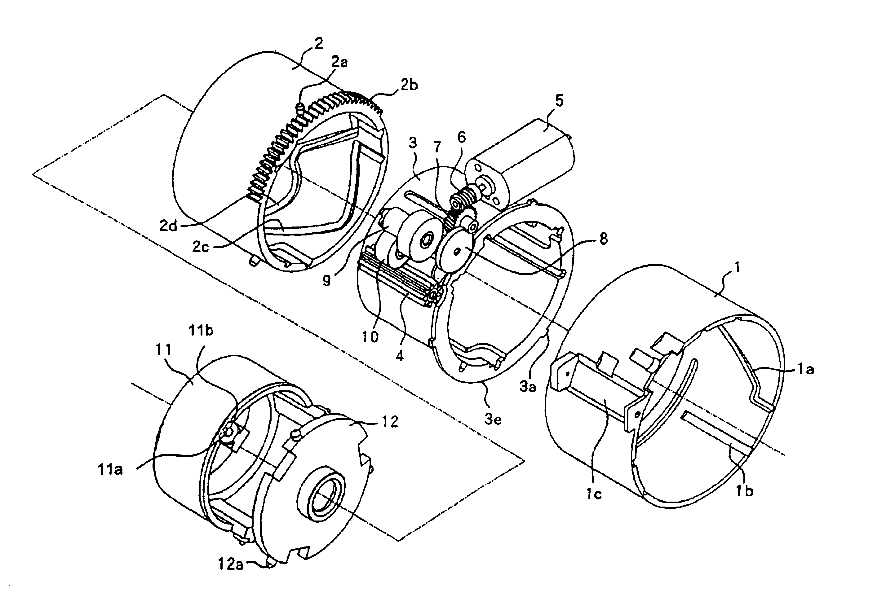
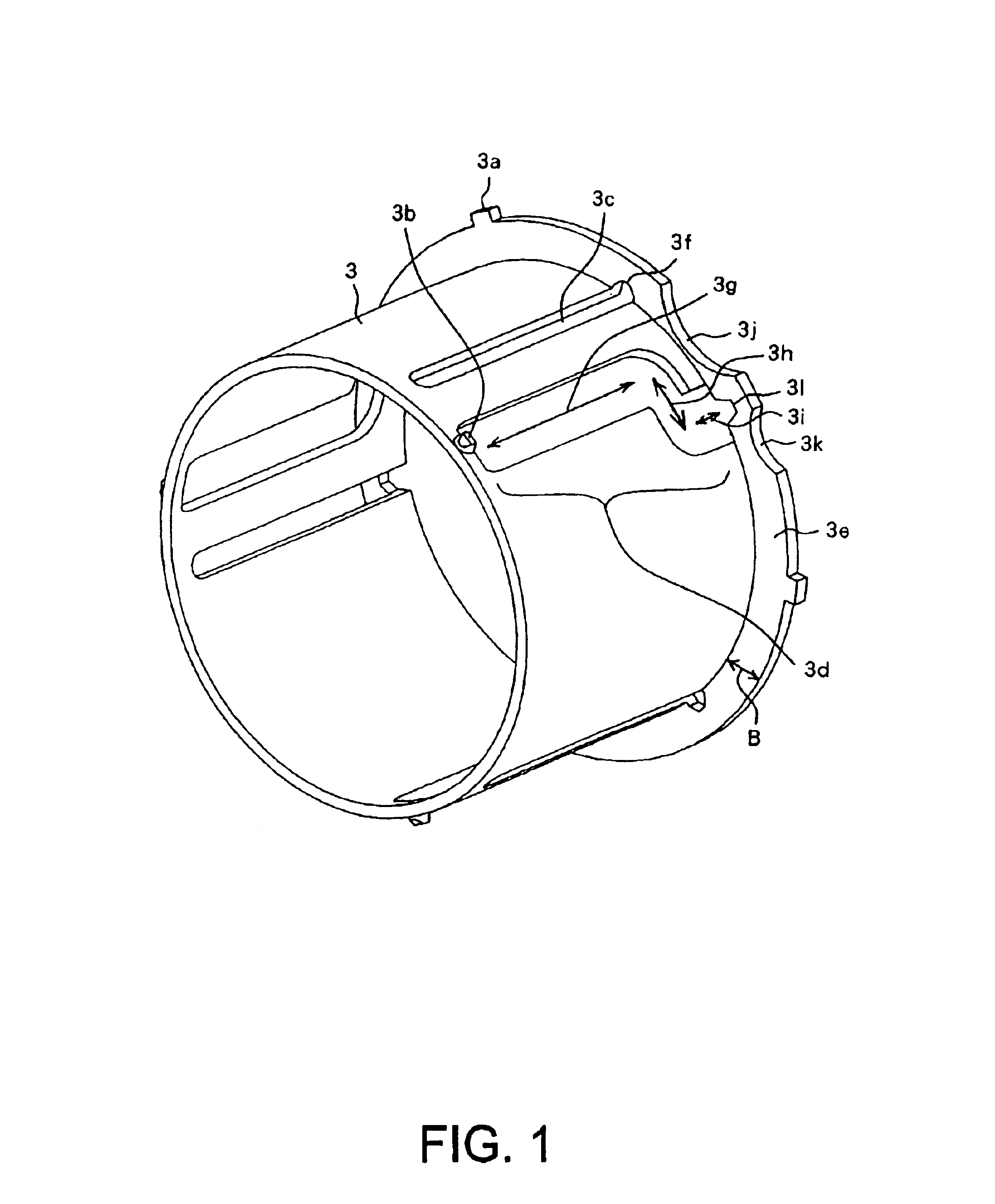
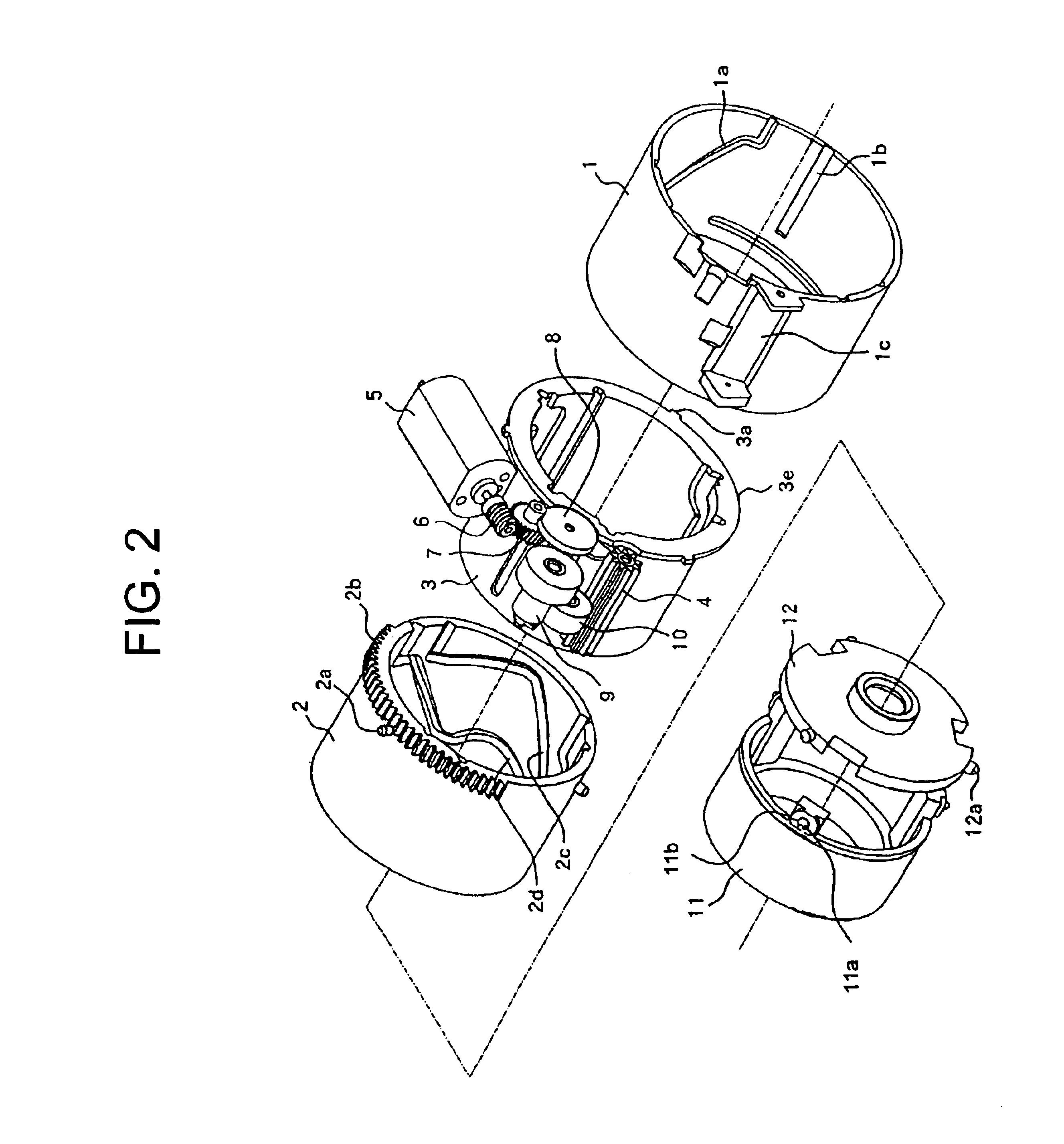
Next discussion is made on an embodiment of the present invention using FIG. 1 through FIG. 4. Now, FIG. 1 is a perspective view of a rectilinear barrel comprising the lens barrel of the present embodiment, and FIG. 2 is an exploded view in perspective of the lens barrel. FIG. 3 is a perspective view of the rectilinear barrel with the first lens unit barrel and the second lens unit barrel are assembled, and FIG. 4 illustrates the manner how the first lens unit barrel moves.

On the right side in the front surface of the camera body 60, a light-emitting window portion 62 that composes a stroboscope which irradiates the subject with an i...


PUM


Abstract

A lens apparatus which is easy to assemble, provides high strength at the flange portion, and achieves high degree of design freedom, too, is disclosed. On the circumferential wall of a second barrel member, a first groove portion is disposed to guide a guide portion provided in the first barrel member and at the end of optical axis direction of the circumferential wall, a flange portion is formed. On a third barrel member, a cam portion which engages with a cam follower portion provided on the guide portion is formed.

Description

1. Field of the InventionThe present invention relates to a barrel mounted to image-taking apparatus such as silver halide camera and digital still cameras, and more specifically video cameras, etc.2. Description of the Related ArtFIG. 6 shows a barrel of a conventional camera (see Japanese Patent Application Laid-Open Publication No. H07(1995)-043584). In the figure, numeral 101 denotes a rectilinear barrel, and this rectilinear barrel 101 is positioned inside a differential barrel not illustrated. When this differential barrel moves in the optical axis direction while the differential barrel rotates around the optical axis, the rectilinear barrel 101 moves in the optical axis direction in linkage with the movement of the differential barrel while the rectilinear barrel 101 does not rotate around the optical axis.To the rectilinear barrel 101, three guide groove portions 101d extending along the optical axis direction are located at nearly even intervals. To guide the groove portio...

Claims


Application Information

Patent Timeline
Patent Type & Authority Patents(United States)
IPC IPC(8): G02B15/14G02B7/04
CPCG02B15/14G02B7/04
Inventor ICHINO, KAZUSHIGE
Owner CANON KK
Why Eureka
Try Eureka