Eureka AIR delivers breakthrough ideas for toughest innovation challenges, trusted by R&D personnel around the world.

Automatic pool cover system using buoyant-slat pool covers

a technology of automatic pool cover and buoyant slat pool cover, which is applied in the direction of curtain suspension device, door/window protection device, shutter/movable grille, etc., can solve the problems of failure of most automatic pool cover system, and failure to overcome passive force during retraction

Inactive Publication Date: 2004-12-07
LAST HARRY J
View PDF8 Cites 13 Cited by
  • Summary
  • Abstract
  • Description
  • Claims
  • Application Information

AI Technical Summary

Benefits of technology

One object of this invention is therefore to provide a means to control the flow of fluid under pressure to the hydraulic motor to limit the travel of the cover. Another object is to enable using a hydraulic motor to drive the cover system without the use of a worm gear reducer as an unwinding braking force.
In order to avoid and overcome the above problems, the present invention provides for a very simple floating cover drive system which overcomes many of the drawbacks with prior floating cover drive systems while obtaining additional advantages and benefits including lower cost, lower construction and installations costs as well as significantly improving the reliability and also the appearance of such systems. This system is also applicable to both hydraulic and electrical cover drives.

Problems solved by technology

Consequently, the overall costs of construction and costs of installation were considerable.
In fact, it has been recognized that at least fifty percent of the failures of most automatic pool cover systems is due to the inherent problem of water damage.
Such passive force systems also have a disadvantage in that the passive force must be overcome during retraction.
It should be understood that in the case of covers mounted in the pool bottom and in particular, the combination of buoyant upward force and the resultant lever or moment arm from the cover drum diametrical buildup can result in high torque requirements on the motor drive system, adding considerable expense.
As with the American cable type automatic cover systems, it has been the experience with the European slat type cover systems, that as high as fifty percent of all automatic cover failure is attributable to moisture damage of the electrical drive and control system.
Since planetary gears have no braking capability and will back drive, a friction brake must be incorporated inside of the drum, with adequate braking capability, adding to the expense.
These arrangements are sold as waterproof systems, but there is little experience as to the durability and life of the seals of these systems and the manufacturers warranties are typically one to two years in duration.
In the case of leakage, damage and the replacement labor cost of these systems is expected to be extensive.
Another concern and disadvantage of electrically powered cover systems is the risk of electrical shock hazard.
In the case of systems where the electric drive motor is in the tube there will also be a shock hazard when the enclosure leaks and floods the motor.
A problem with low voltages is that the current carrying capacity is low and therefore for long distances away from the pool the cable thickness requirements will be high, expensive and impractical.
Because it is often difficult for the operator to precisely see when to stop the cover movement, various forms of electric limit switches and sensors are used to precisely stop the cover automatically.
This means that rotary revolution counting limit switches, such as described in U.S. Pat. No. 3,718,215, coupled to the gear motor shaft, are usually inaccurate and unreliable.
Because covers stretch, accumulate dirt and debris, electric control wires snag and break.
As a result this type of limit switch is often very unreliable.
As with the cable type pool covers, slat covers will sometimes use sensor type of limit switches and generally experience the same problems with the environment as described above.
As described above, this is typically a problem in a swimming pool environment.
However, these devices are concerned primarily with high speed operation and low torque operation.
Little use has been made of hydraulic motors in the buoyant type of cover to date because of the following problems.
One problem with the slat cover, is that there is a constant buoyant force or a gravity force on the cover in the covering direction.
These counterbalance hydraulic valves include normally closed valves which are opened only when a preset pilot pressure is reached.
Although these brake valves and pilot valves can act as forms of check valves, they will not maintain a motor in a locked condition.
Although the hydraulic motor can prevent rotation better than electric motors by blocking fluid flow on the inlet and outlet ports, there is still enough internal leakage in the motor to cause some creep of the motor shaft when subjected to constant load at rest, such as the torque on the shaft from the buoyant force or gravitational force of a floating pool cover.
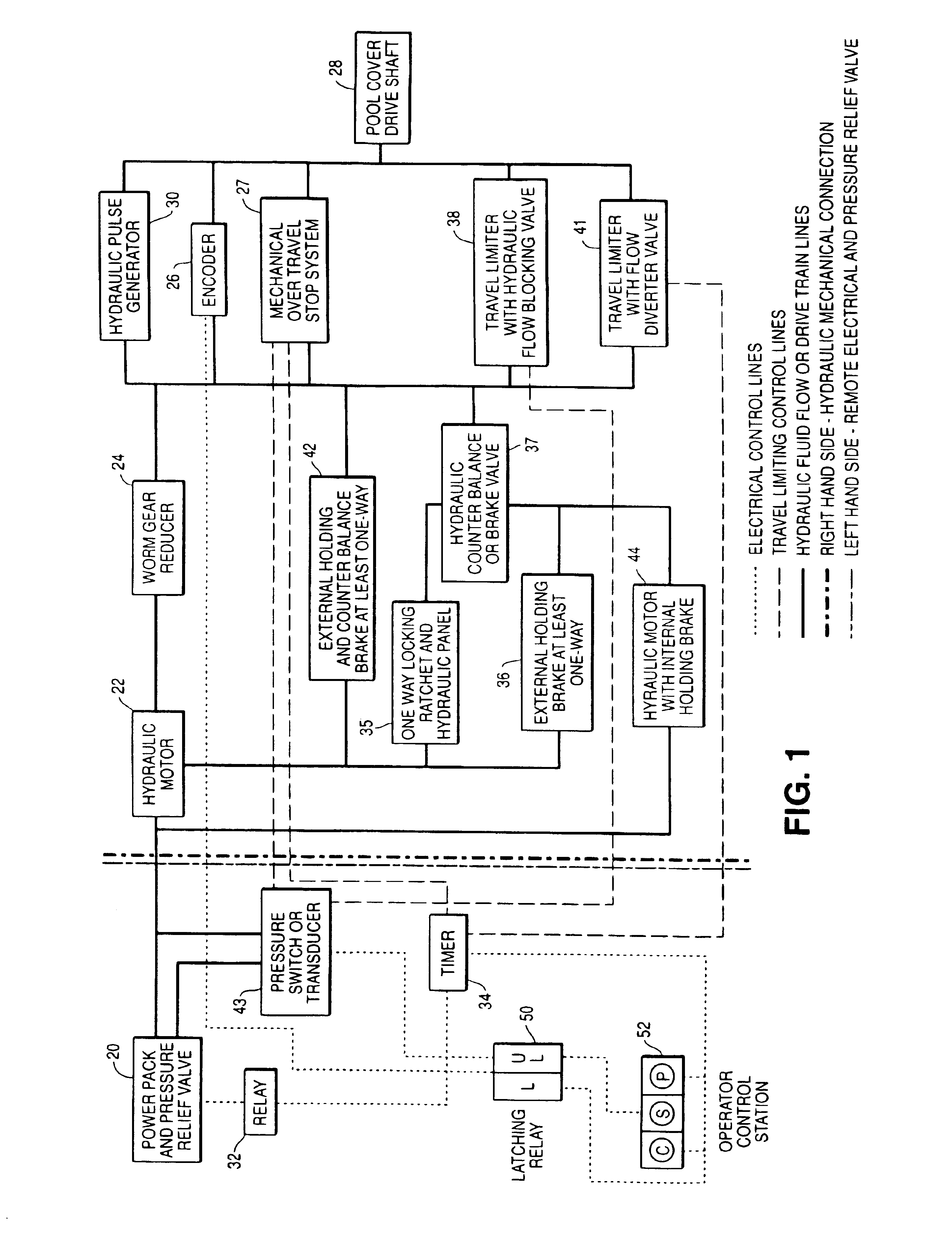
As a result, either a more expensive hydraulic brake motor with additional control systems must be used, or the motor must be coupled with an additional cost worm gear reducer to provide braking, as used with the electric drive motors.
Adding a worm gear reducer, for braking only, can add considerably to the cost of the drive system.
Furthermore, for the reducer to act as a brake it must also possess high internal frictional resistance and must be inefficient.
This further means that the pump must also put out a substantially higher volume of fluid, which generally increases the cost of the power pack.
Moreover, it becomes a rather costly component to serve as a brake when, indeed, it is not highly efficient for providing braking power.
Thus, the gear reducer can become a very costly component and merely function as a brake.
Consequently, use of the reducer is highly inefficient.
This however requires running electrical control cabling with inherent shock hazard at the pool.
Also moisture problems as described above will negate the advantage and reliability of using the hydraulic drive motor.
Since there is not a cable pulling the cover to a closed position, the cover cannot be used as a positive stopping means to activate a hydraulic pressure relief valve.
This device is also complex in construction and uses a two part traveling nut with a pair of concentric jack screws to prevent jamming of this high speed high torque device.
However, some travel limiting mechanism of the type described herein would necessarily have to be employed.
This would, in turn, cause cessation of the operation of the hydraulic motor 22.

Method used


Image

  • Automatic pool cover system using buoyant-slat pool covers
  • Automatic pool cover system using buoyant-slat pool covers
  • Automatic pool cover system using buoyant-slat pool covers

Examples


Embodiment Construction

1. Operator control switches 52. Manually operable operator control switches including a start switch and a stop switch and a type of emergency open switch and which are only manually operable by an operator. These switches may be latching switches or switches which do not latch. Latching circuits can be provided for this purpose.

2. Latching relays 50. Latching relays may be used in combination with the operator control switches and the latching circuits. The latching relays may usually constitute latch and unlatch states for operation of the components being actuated by an electrical signal.

3. Timer 34 (Time-out circuit). A timing circuit to break a control circuit at a pre-set time interval and stop the cover or pump from operating.

4. Pressure relief valve. A hydraulic control valve which will divert pressurized hydraulic flow back to a reservoir at a preset pressure point.

5. Power pack 20. The power pack may be operated with a directional valve or reversible motor to reverse the ...


PUM


Abstract

A drive and control system for controlling the movement of a pool cover comprised of interconnected rigid buoyant slats. The system relies upon a hydraulic drive section including a hydraulic motor drive which may be initially provided with fluid under pressure by a remote electric drive section. The hydraulic drive section is also provided with an effective means of controlling movement of the pool cover, both in a winding direction on a cover drum, which may be submerged, and / or in an unwinding direction where the pool cover is being unwound from the drum. Various mechanisms to control the movement of the cover are described herein.

Description

1. Field of the InventionThis invention relates in general to certain new and useful improvements in automatic swimming pool cover system and, more particularly, to a cover system using a hydraulic drive for slatted buoyant type pool covers.2. Brief Description of Related ArtPool covers are used on many swimming pools. They save energy, keep the pool clean, minimize chemical use and provide desirable safety features. In fact, in windy locations, a pool cover is essential for maintaining pool water at comfortable temperatures at a reasonable expense.The types of commercially available pool covering systems and those which have been proposed include free floating covers, tie down / stretched covers and track anchored floating covers. Mechanisms for retracting such covers back and forth across a pool include purely manual devices such as the "Rocky's" roller manufactured B. C. Leisure Ltd. 113-1305 Welch Street North Vancouver B.C. Canada V7P 1B3; semi-automatic systems (see U.S. Pat. No...

Claims


Application Information

Patent Timeline
Patent Type & Authority Patents(United States)
IPC IPC(8): E04H4/10E04H4/08E04H4/00
CPCE04H4/101E04H4/082
Inventor LAST, HARRY J.
Owner LAST HARRY J
Why Eureka
Eureka Blog
Learn More