IC socket assembly

a socket assembly and integrated circuit technology, applied in the direction of coupling device connection, coupling device details, coupling/disengagement parts, etc., can solve the problems of decreasing the distance of the pins of the two adjacent contacts, and increasing the difficulty of making holes in the burn-in board. , to achieve the effect of reducing the difficulty of making

Inactive Publication Date: 2004-12-21
HON HAI PRECISION IND CO LTD
View PDF10 Cites 10 Cited by
  • Summary
  • Abstract
  • Description
  • Claims
  • Application Information

AI Technical Summary

Benefits of technology

, an IC socket assembly in accordance with a preferred embodiment of the present invention is used for electrically connecting an IC with a burn-in board having a multiplicity of holes extending therethrough in a vertical direction. The IC socket assembly comprises an insulative housing, a holding component assembled in the housing and a multiplicity of electrical terminals received in the holding component. Each of the terminals comprises a head portion forming a first contact portion at a free end thereof for electrically contacting the IC, a holding portion engaging the terminal in the holding component, and a second contact portion for electrically contacting the burn-in board by Through Hole technology. Some of the terminals further comprise connecting portions each bending from ends of the holding portions to ends of the second contact portions. Each of the connecting portions extends a desired distance in a horizontal direction, such that a distance between two adjacent second contact portions in one row is larger than a distance between two adjacent first contact portions in one row. Therefore, it is likely to decreases the difficulty of making the holes in the burn-in board and assembling the second contact portions into the burn-in board by Through Hole technology.

Problems solved by technology

Accordingly, a distance of the pins of the two adjacent contacts is decreasing, which increases the difficulty of making holes in the burn-in board and assembling the contacts onto the burn-in board by Through Hole technology.
Therefore, it is likely to decreases the difficulty of making the holes in the burn-in board and assembling the second contact portions into the burn-in board by Through Hole technology.

Method used


Image

  • IC socket assembly
  • IC socket assembly
  • IC socket assembly

Examples


Embodiment Construction

Reference will now be made to the drawings to describe the present invention in detail.

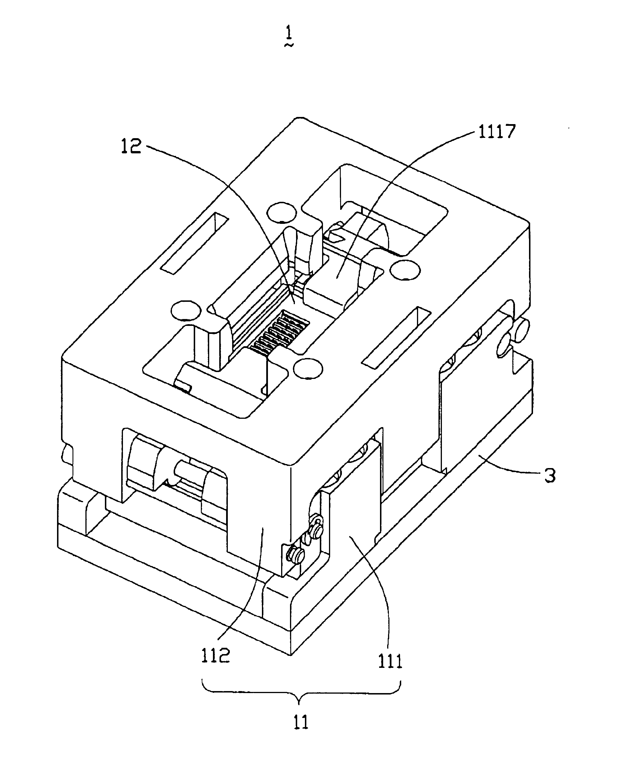
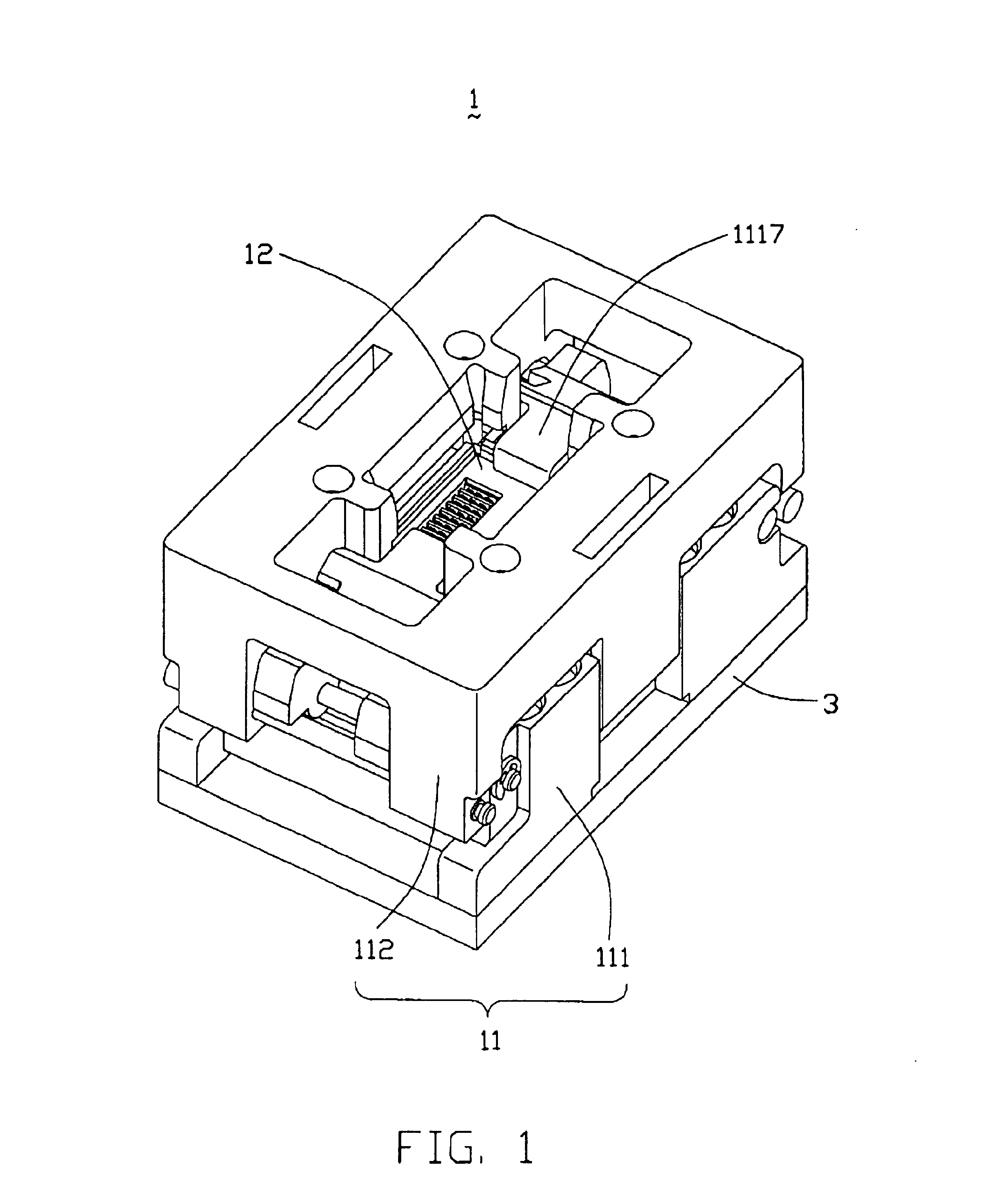
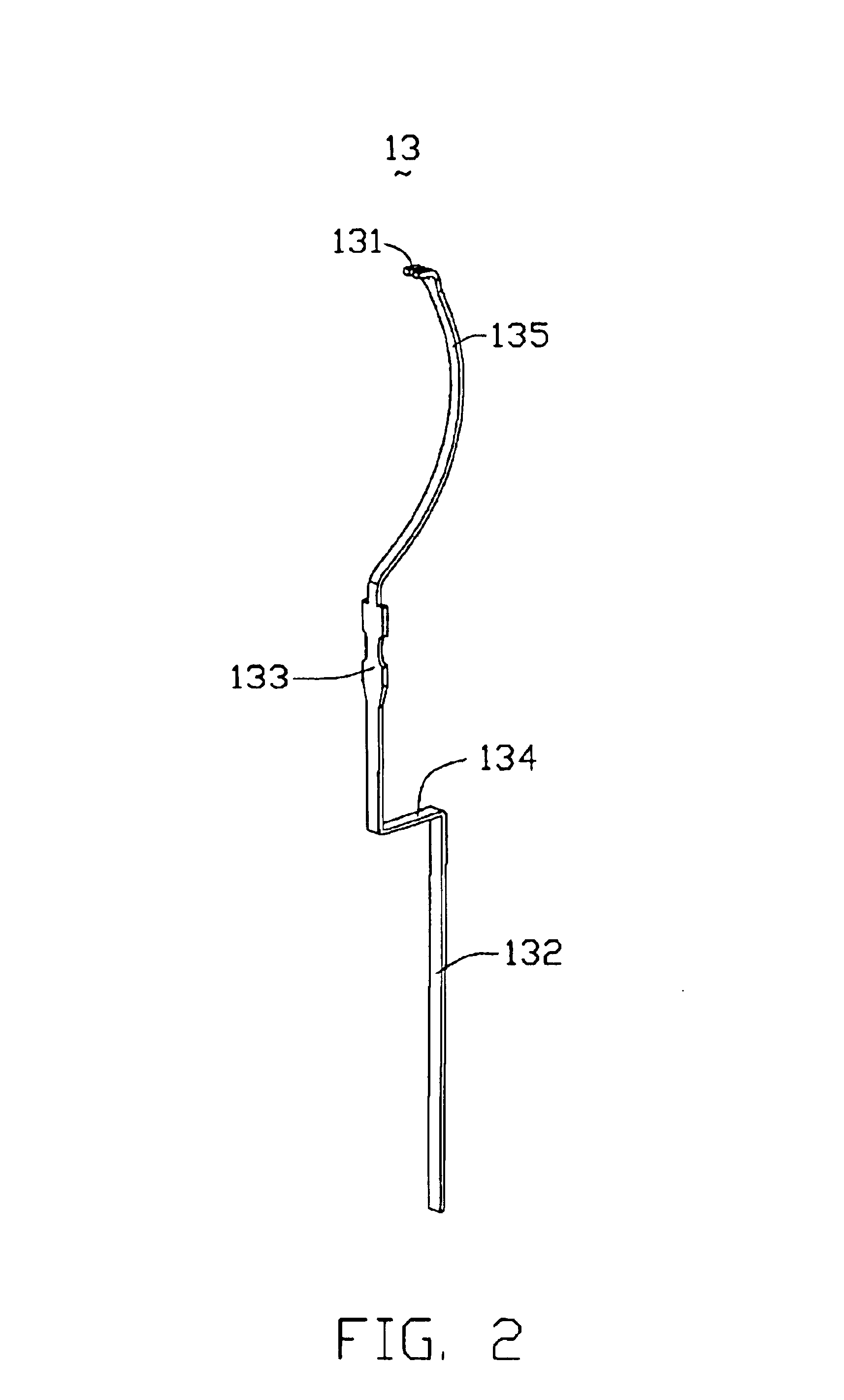
Referring to FIGS. 1 through 5 and 10 through 12, An integrated circuit (IC) socket assembly 1 in accordance with the preferred embodiment of the present invention is used for electrically connecting an electronic package such as an IC 2 with a circuit substrate such as a burn-in board 3. The IC socket assembly 1 comprises an insulative housing 11, a holding component 12, a plurality of electrical terminals, and a pair of pushing members 1117. Referring to FIG. 9, the burn-in board 3 defines four first holes 31 in four corners of a rectangle respectively, a pair of second holes 32 defined in a portion between two first holes 31 in a width of the rectangle, and a plurality of third holes 33 defined in a middle of a portion surrounded by the rectangle and arranged in six rows rectangular. Each of the first, second and third holes 31, 32, 33 extends through the burn-in board 3 in a vertical direction...


PUM


Abstract

An integrated circuit (IC) socket assembly (1) includes an insulative housing (11), a holding component (12) and a multiplicity of electrical terminals (13). Each of the terminals includes a head portion (135) forming a first contact portion (131) at a free end thereof for electrically contacting an IC (2), a holding portion (133) engaging the terminal in the holding component, and a second contact portion (132) for electrically contacting a burn-in board (3) by Through Hole technology. Some of the terminals further include connecting portions (134) each bending from ends of the holding portions to ends of the second contact portions. Each of the connecting portions has a desired length in a horizontal direction, to decreases the difficulty of making the holes in the burn-in board and assembling the second contact portions into the burn-in board by Through Hole technology.

Description

1. Field of the InventionThe present invention relates to an integrated circuit (IC) socket assembly for electrically connecting an electronic package such as an IC with a substrate circuit such as a burn-in board.2. Description of the Prior ArtElectronic packages, such as integrated circuits (ICs), are miniaturized electronic devices in which a number of active and passive circuit elements are located on or within a continuous body of material to perform the function of a complete circuit. To ensure reliability in use, the ICs require prior burning in to test their durability. The ICs are operated at high temperature for an extended period of time to accelerate potential failure points. This helps eliminate early product failures once the ICs are sold and / or assembled onto electronic end products. Consequently, an IC socket assembly is used to receive an IC therein, and to electrically connect the IC with a burn-in board for operation of the IC at high temperature. Pertinent exampl...

Claims


Application Information

Patent Timeline
Patent Type & Authority Patents(United States)
IPC IPC(8): H01R4/02H01R13/631H01R43/02
CPCH01R4/02H01R43/0249H01R13/6315
Inventor HOU, SUNG-PEI
Owner HON HAI PRECISION IND CO LTD
Why Eureka
Try Eureka