Refrigerator using double suction type centrifugal blower

Active Publication Date: 2005-01-04
LG ELECTRONICS INC
View PDF1 Cites 12 Cited by
  • Summary
  • Abstract
  • Description
  • Claims
  • Application Information

AI Technical Summary

Benefits of technology

An object of the present invention is to provide a refrigerator increasing a floor area ratio of a freezing chamber.
Another object of the present invention is to provide a refrigerator increasing a utilization rate of heat transfer area.

Problems solved by technology

However, the conventional refrigerator has problems as followed.

Method used


Image

  • Refrigerator using double suction type centrifugal blower
  • Refrigerator using double suction type centrifugal blower
  • Refrigerator using double suction type centrifugal blower

Examples


first embodiment

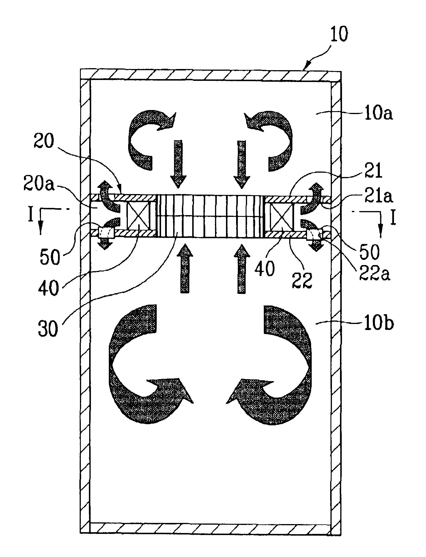
Hereinafter, the present invention is explained in detail. A refrigerator according to the present invention includes a cabinet 10, a mullion 20, double suction centrifugal blower 30 and outlets 21a and 21b.

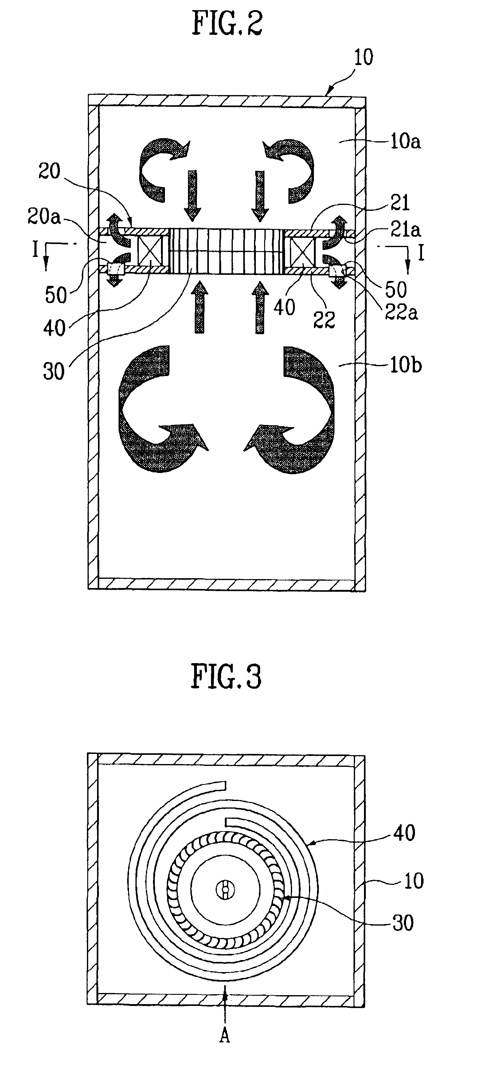
As illustrated in FIGS. 2 and 3, the cabinet has a storage space inside and the mullion 20 dividing the cabinet into a freezing chamber 10a and refrigerator chamber 10b. The mullion 20 is formed in double diaphragm and includes a top panel 21 and a bottom panel 22. A cold airflow passage is formed between the panels 21 and 22.

The double suction centrifugal blower 30 is an apparatus for sucking air from the middle thereof and discharging the sucked air to both sides thereof, and provided at a part vertically passing through the central part of the mullion 20. The evaporator 40 is provided at the cold airflow passage 20a for exchanging heat with air exhausted from the double suction centrifugal blower 30. A top outlet passage 21a and a bottom outlet passage 22a are provided at a t...

second embodiment

The refrigerator includes the cabinet 10, the mullion 20, the double suction centrifugal blower 30, the top outlet 21a, the bottom outlet 22a, the evaporator 40 and the cool air duct 60 in the second embodiment in FIG. 6.

Here, a structure of the mullion and the evaporator is the same as that in the first embodiment. Therefore, only is a composition of the cool air duct explained in the second embodiment.

The cool air duct 60 is a passage of cool air and is provided to transmit cool air evenly in the refrigerator. Therefore, the cool air duct 60 is connected to the outlet 22a on the refrigerator chamber side in the cold airflow passage, extended from top to bottom of the refrigerator chamber 10b, and is provided on the side or at rear of the refrigerator chamber 10b. A plurality of aperture 60a is provided in the cool air duct 60a. Cool air is exhausted through a cool air through-hole 60a. Therefore, cool air is diffused into the refrigerator better than when cool air is exhausted str...


PUM


Abstract

This invention is to increase a floor area ratio of a freezing chamber and a utilization rate of heat transfer. A refrigerator is disclosed, which includes a cabinet having a storage space, a mullion provided in the cabinet to divide the storage space into a freezing chamber and a refrigerator chamber, the mullion having a cold airflow passage provided therein that is communicated with the freezing chamber and the refrigerator chamber, a double suction centrifugal blower provided in a middle space of the mullion and sucking air from the freezing chamber and the refrigerator chamber and exhausting to the cold airflow passage, an evaporator provided in the cold airflow passage for exchanging heat with the air exhausted from the double suction centrifugal blower, a top outlet and a bottom outlet exhausting air being passed through the evaporator to the freezing chamber and the refrigerator chamber.

Description

CROSS-REFERENCE TO RELATED APPLICATIONSThis application claims the benefit of Korean Application No. P2002-0078291, filed on Dec. 10, 2002, which is hereby incorporated by reference as if fully set forth herein.BACKGROUND OF THE INVENTION1. Field of the InventionThe present invention relates to a refrigerator, and more particularly, to a refrigerator using a double suction centrifugal blower.2. Discussion of the Related ArtIn general, a refrigerator is an apparatus for taking storage of foods freshly for a long-term period. As illustrated in FIG. 1, a refrigerator includes an evaporation chamber 3 having a cabinet 1, a mullion 2, an evaporator 3a and a fan 3b and an apparatus chamber having a refrigerant duct, a compressor and a condenser.Explaining the composition of the refrigerator, the cabinet 1 has a storage space inside. The mullion 2 divides the storage space in the cabinet into a freezing chamber 1a and refrigerator chamber 1b. The cold airflow passage is formed in the mulli...

Claims


Application Information

Patent Timeline
IPC IPC(8): F25D17/04F25D17/06
CPCF25D17/045F25D17/065F25D2317/0653F25D2400/04F25D2317/0681F25D2317/0683F25D2317/0664F25D17/06
Inventor LEE, SANG WOOK
Owner LG ELECTRONICS INC
Why Eureka
Try Eureka