Power booster fuel saver

a fuel saving and power booster technology, applied in the direction of fuel re-atomisation/homogenisation, charge feed system, combustion engine, etc., can solve the problems of large amount of fuel consumed by large vehicles, poor fuel economy, inefficient gas flow, etc., and achieve the effect of improving vehicle performan

Inactive Publication Date: 2005-01-04
BURNETT DAVID T
View PDF13 Cites 47 Cited by
  • Summary
  • Abstract
  • Description
  • Claims
  • Application Information

AI Technical Summary

Benefits of technology

The present invention is directed to a power booster fuel saver in which a strip of stainless steel is cut and bent into a cylindrical shape that is capable of being inserted into a vehicle inlet or exhaust pipe and that improves the vehicle performance during normal operation of the vehicle. The types of vehicles which can benefit by this device include large tractors, diesel locomotives, outboard boat motors and lawnmowers, including both turbo-boosted and carbureted vehicles.
It is an object of the invention to provide improved elements and arrangements thereof in an apparatus for the purposes described which is inexpensive, dependable and fully effective in accomplishing its intended purposes.

Problems solved by technology

Present-day large vehicles, like tractors, diesel trucks and diesel locomotive consume large amounts of fuel.
Therefore, the pattern of air or gas flow through the intake or exhaust is generally turbulent, thereby contributing to inefficient gas flow and resulting in poor fuel economy.

Method used


Image

  • Power booster fuel saver
  • Power booster fuel saver
  • Power booster fuel saver

Examples


Embodiment Construction

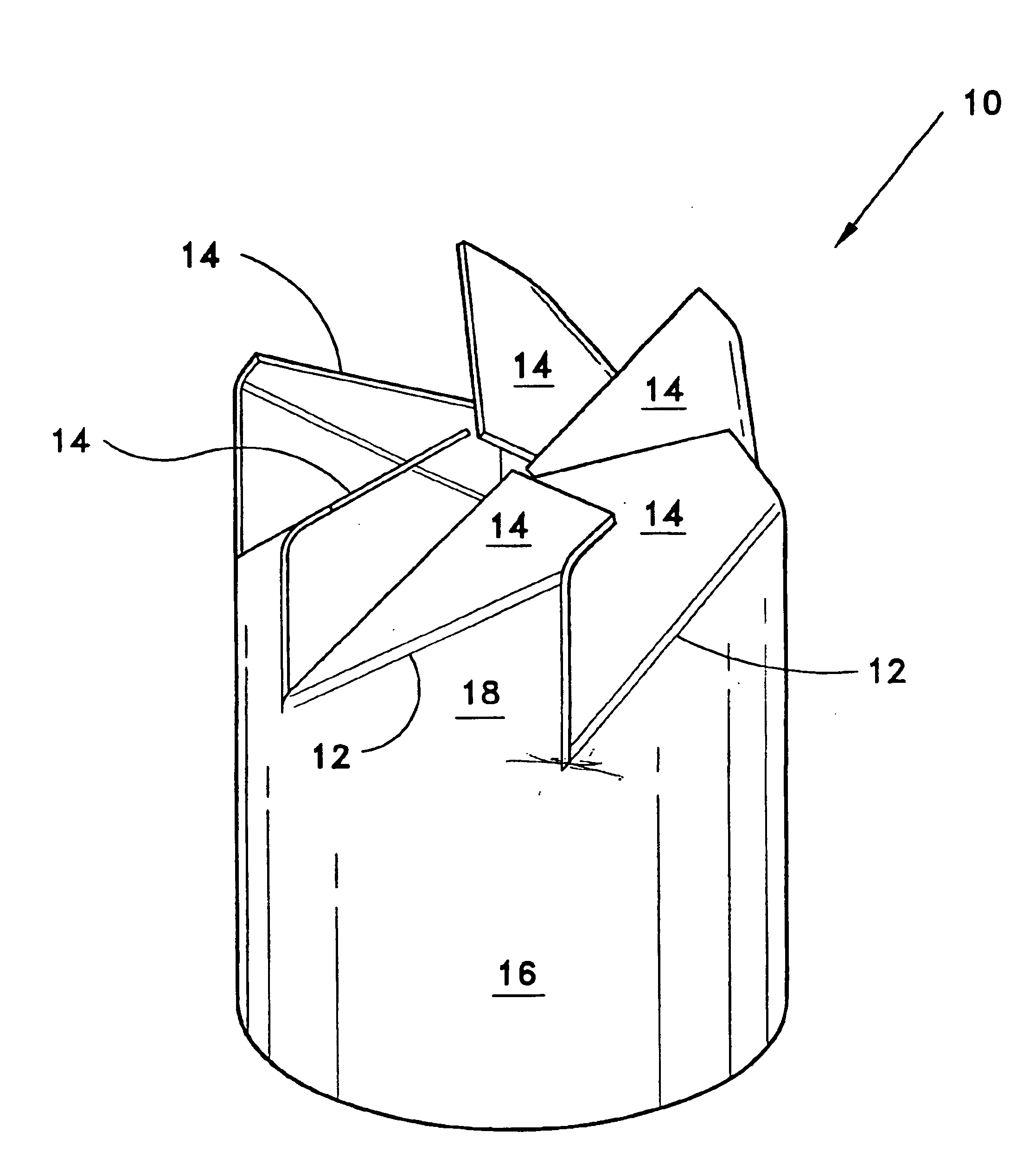
FIG. 1 shows a power booster fuel saver 10 according to the present invention showing its cylindrical shape. The structure is a made from a single strip of Grade 304 or 316 stainless steel with a thickness of 25 mil for large trucks or 10 mil for other automotive vehicles. Tabs 18 extend from the remaining skirt 16 of the cylindrical structure 10. Each tab 18 is bent diagonally along folds 12 to produce dog-ears 14 that are oriented in an upward direction from the page.

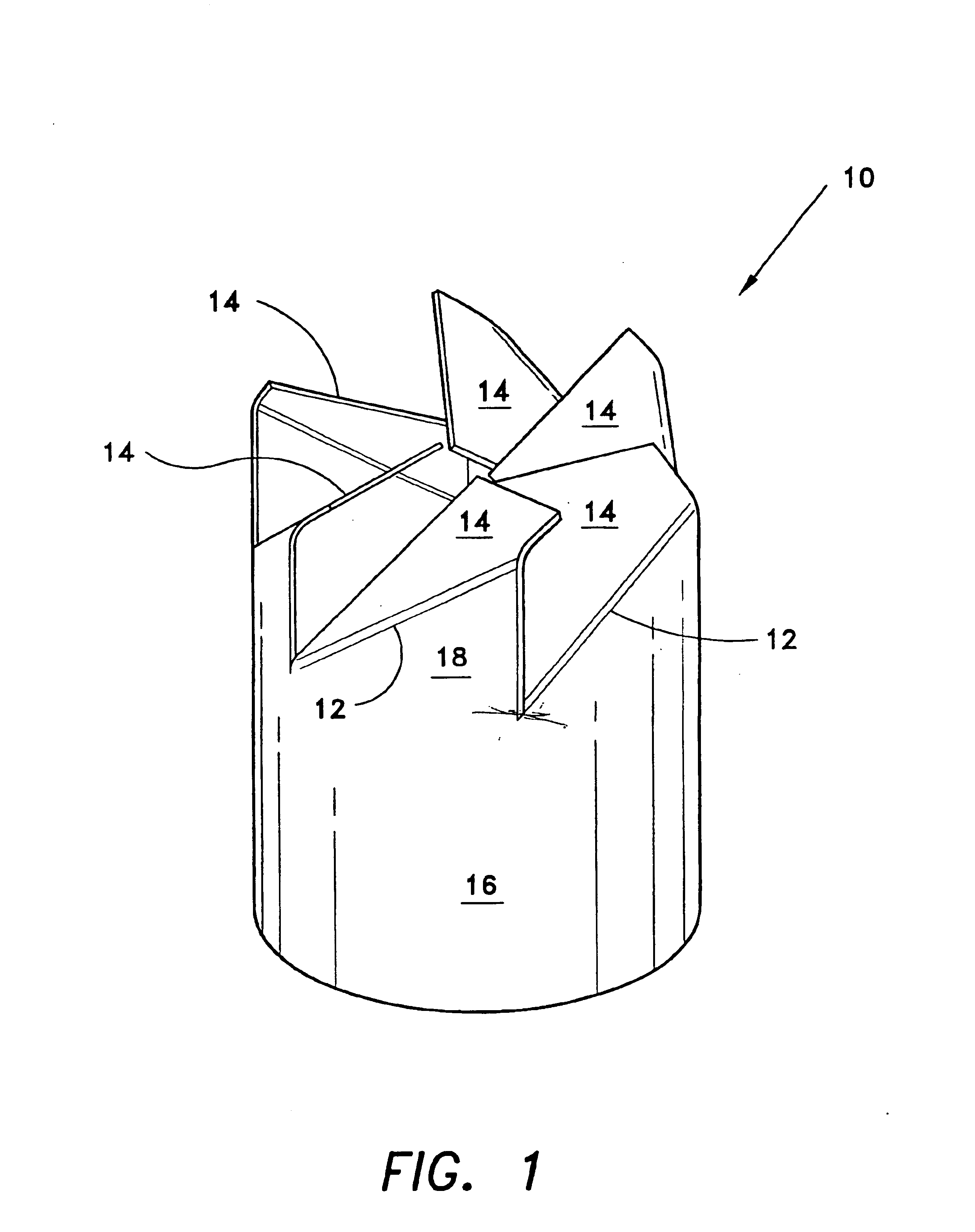
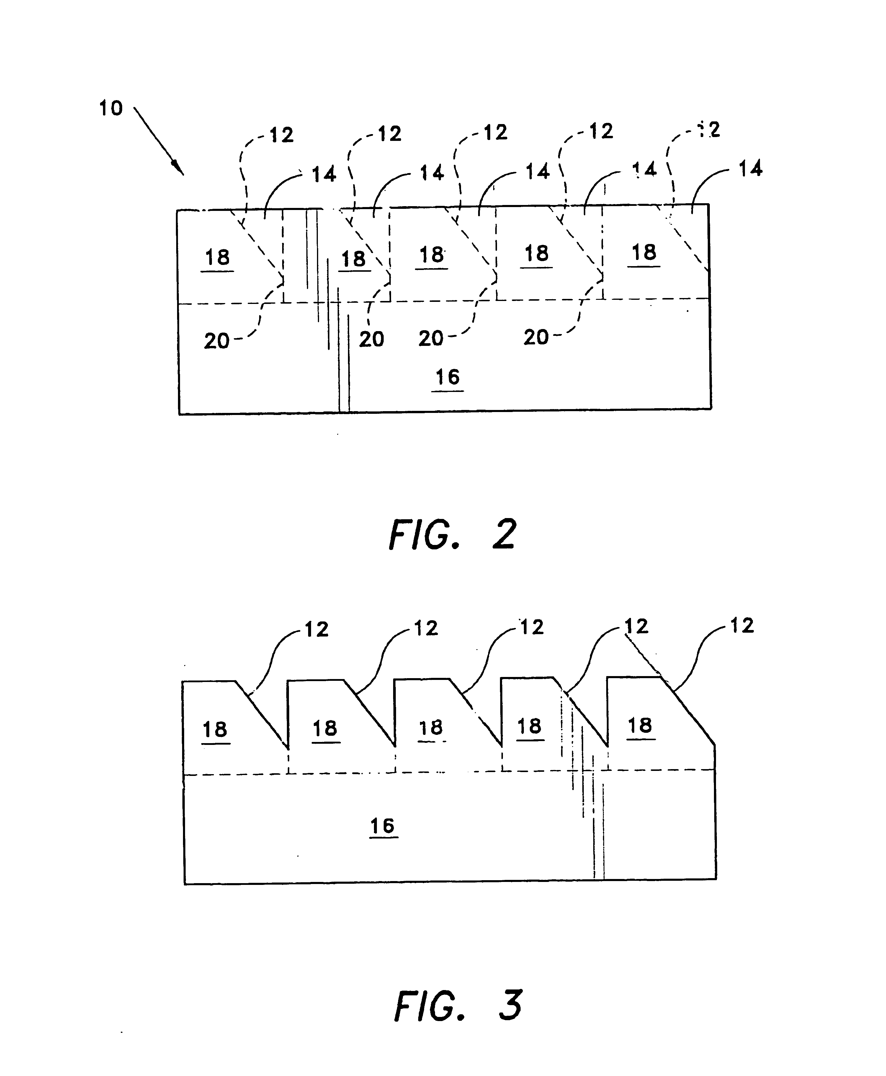
Referring to FIG. 2, the starting strip of stainless steel, preferably grade 304 or 316, and preferably 10 mil or 25 mil in thickness, depending upon application, is initially cut along cut lines 20 to form square-shaped tabs 18 that extend from the skirt 16, as shown in FIG. 3. The strip is shaped and joined at the ends to form a cylinder, and the tabs 18 are bent radially inward in overlapping fashion to form the fuel saver 10. Grade 304 or 316 stainless steel is preferred, rather than carbon steel, so that stress f...


PUM


Abstract

The power booster fuel saver is made of a cut and formed piece of stainless steel in the shape of a cylinder. The strip is provided in a length sufficient to correspond to the inner diameter of the inlet pipe to a vehicle engine or from its turbo fan outlet, or into the inlet pipe leading to the turbo fan or in the exhaust pipe from the engine. A series of square-shaped tabs are cut along one side of the strip and then bent diagonally to form a series of dog-ears. Finally, the strip is rolled into the shape of a cylinder in which the edges meet and the resulting device is inserted into the intake of a vehicle.

Description

BACKGROUND OF THE INVENTION1. Field of the InventionThe present invention relates to an insertable device for creating a vortex in a vehicle inlet or exhaust pipe, in order to enhance vehicle performance, e.g., to boost power and save fuel. More particularly, the vortex-creating device is made of a strip of Grade 304 or 316 stainless steel that is cut to form bent tabs and shaped into a cylinder that can be inserted permanently into a vehicle air intake or exhaust pipe.2. Description of Related ArtThe invention is directed to an insertable device in which a strip of Grade 304 or 316 stainless steel is cut and bent into a cylindrical shape that is capable of being inserted into a vehicle inlet or exhaust pipe and that improves the vehicle performance during normal operation of the vehicle by creating a rotating gaseous vortex.U.S. Pat. No. 830,268 issued to Wheelock on Sep. 4, 1906 teaches a insertable device for improving the circulation in U.S. Pat. No. 1,115,699 issued to Loose on...

Claims


Application Information

Patent Timeline
Patent Type & Authority Patents(United States)
IPC IPC(8): F02B31/00F02M29/00F02M29/06
CPCF02B31/00F02M29/06Y02T10/146Y02T10/12
Inventor BURNETT, DAVID T.
Owner BURNETT DAVID T
Why Eureka
Try Eureka