Structure of liquid crystal display (LCD)

a liquid crystal display and height structure technology, applied in the direction of instruments, furniture parts, electric apparatus casings/cabinets/drawers, etc., can solve the problems of user discomfort, time-consuming and labor-intensive adjustment of table height, and user may still have to be seated in an uncomfortable position

Inactive Publication Date: 2005-01-04
WU WEI CHUNG +1
View PDF8 Cites 124 Cited by
  • Summary
  • Abstract
  • Description
  • Claims
  • Application Information

AI Technical Summary

Benefits of technology

Accordingly, it is an object of the present invention to provide a Liquid Crystal Display (LCD) structure comprising a display; an adjustment device having a securing rod with two ends mounted with a hinge chain module; a seat body including an engaging slot and a positioning slot; a support rod including a positioning rib, thereby one side of the display is connected to the chain module of the adjustment device the securing rod being connected to one end of the support rod, a second end of the support rod is connected to the engaging slot, the positioning rib is extended to the positioning slot of the seat body so that the LCD can be adjusted.

Problems solved by technology

An LCD without an adjustable height structure may not be suitable for users who are particularly short or tall in height.
As a result, adjusting the height of the table can be time consuming.
Even if the height of the table is adjusted, the user may still have to be seated in an uncomfortable position in order to operate the computer for a prolonged period.
However, one common drawback of these two LCDs is that the structure is complicated and therefore, it is very laborious. to install.
This will cause an increase in the cost of production.
Additionally, the adjusting the height of the LCD is not convenient.
The weight of the LCD has been increased which not only takes up more space but also causes greater inconvenience in its transportation.

Method used


Image

  • Structure of liquid crystal display (LCD)
  • Structure of liquid crystal display (LCD)
  • Structure of liquid crystal display (LCD)

Examples


Embodiment Construction

The following descriptions are of exemplary embodiments only, and are not intended to limit the scope, applicability or configuration of the invention in any way. Rather, the following description provides a convenient illustration for implementing exemplary embodiments of the invention. Various changes to the described embodiments may be made in the function and arrangement of the elements described without departing from the scope of the invention as set forth in the appended claims.

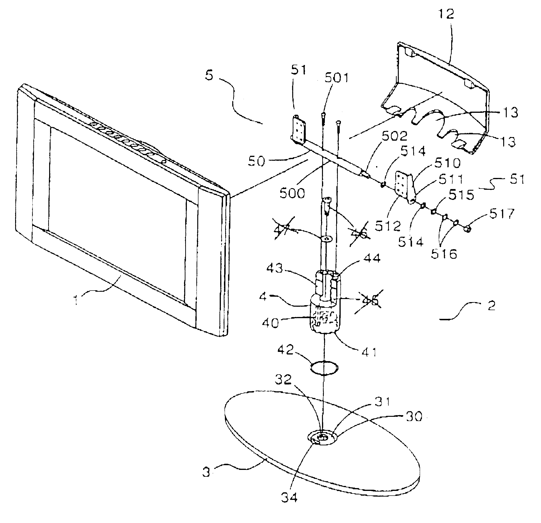
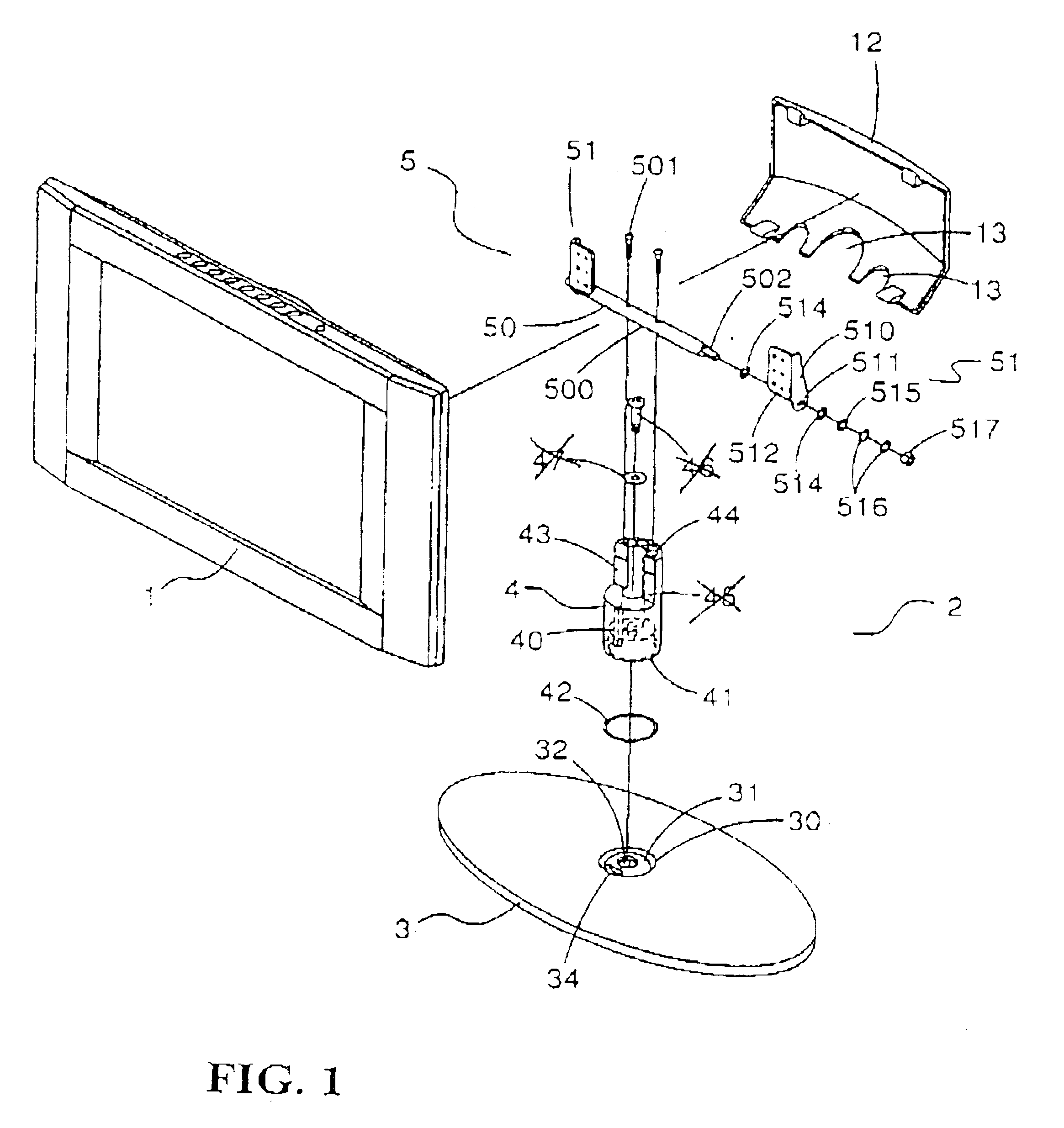
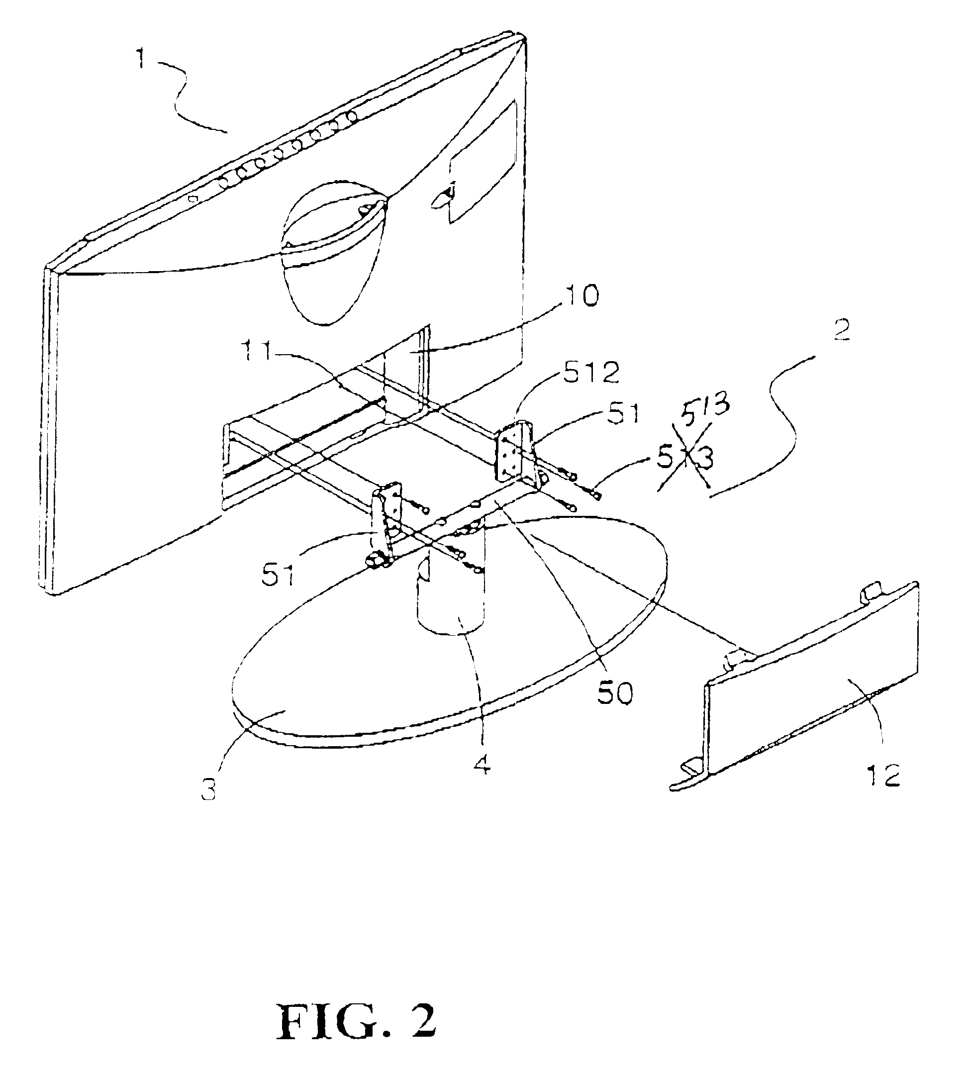
Referring to FIGS. 1 to 4, there is shown a display structure for supporting display 1 so as to adjust the rotation of the display 1 and the angle of the display.

In accordance with the present invention, the display 1 includes a recess 10 at the rear side thereof and the recess 10 is provided with a plurality of screw holes 11 for the mounting of the adjustment device 5 onto the securing seat 510 with screws 513, and the top of the recess 10 is covered with a rear cover 12, and the bottom section of th...


PUM


Abstract

A liquid crystal display (LCD) structure which includes a display; an adjustment device having a securing rod with two ends mounted with a hinge chain module; a seat body including an engaging slot and a positioning slot; a support rod including a positioning rib, thereby one side of the display is connected to the chain module of the adjustment device, with the securing rod being connected to one end of the support rod, the support rod corresponding to the other end of the adjustment device is connected to the engaging slot, the positioning rib is extended to the positioning slot of the seat body so that the LCD can be adjusted The hinge chain module includes a securing seat mounted with positioning holes for the positioning shaft, the ends of the positioning holes are extended outwardly to form a fan-like shape, the securing seat is disposed with a securing plate which can be mounted on the display, the two lateral sides of the securing seat are mounted with two damping pads and the external side of the damping pads is provided with an elastic pad and at least one pressing pad mounted by way of a screw nut to the end of the positioning shaft.

Description

BACKGROUND OF THE INVENTION(a) Technical Field of the InventionThe present invention relates to an Liquid Crystal Display (LCD), and in particular, to an LCD support which allows an LCD to be adjusted and a bottom seat for adjusting the elevational angle of an LCD. The present invention is a bottom seat of an LCD which has a simple structure and lowers the cost of production.(b) Description of the Prior ArtAn LCD without an adjustable height structure may not be suitable for users who are particularly short or tall in height. One way of overcoming this problem of a fixed height LCD is by adjusting the height of the table or desk supporting the display. It is very common for the desk or the table to have many articles or objects on it, such as the host computer, printer, etc. As a result, adjusting the height of the table can be time consuming. Even if the height of the table is adjusted, the user may still have to be seated in an uncomfortable position in order to operate the comput...

Claims


Application Information

Patent Timeline
Patent Type & Authority Patents(United States)
IPC IPC(8): F16M11/08F16M11/06F16M11/02F16M11/10G06F1/16
CPCF16M11/06F16M11/08F16M11/10F16M11/22G06F1/1601F16M11/126Y10S248/923G06F2200/1612
Inventor WU, WEI CHUNGLIN, HWANG PING
Owner WU WEI CHUNG
Why Eureka
Try Eureka