Bullet trapping medium and system

a technology of a trapping medium and a system, which is applied in the direction of bullet catchers, weapons, targets, etc., can solve the problems of affecting the ph of the sap gel, the inability to use dirt berms behind the targets, and the inability to manufacture and maintain systems, so as to reduce the likelihood of ricochet, reduce the probability of ricochet, and reduce the risk of ricochet

Inactive Publication Date: 2005-01-04
ARMY UNITED STATES GOVERNMENT AS REPRESENTED BY THE SEC OF THE
View PDF13 Cites 11 Cited by
  • Summary
  • Abstract
  • Description
  • Claims
  • Application Information

AI Technical Summary

Benefits of technology

It is another object of the present invention to provide a bullet trapping system that substantially reduces the likelihood of ricochets.
Still another object of the present invention is to provide a bullet trapping system that will not leach heavy metals into the environment.
Yet another object of the present invention is to provide a bullet trapping system that can accommodate many different calibers and types of bullets.
A further object of the present invention is to provide a bullet trapping system that requires minimal maintenance over an extended useful life.
The present invention is a backstop for decelerating and trapping projectiles. The backstop generally includes a support structure having an inclined surface and a projectile trapping medium disposed on the inclined surface. The projectile trapping medium may be either a resilient granular ballistic medium, such as rubber chunks, plastic scrap, or wood chips, or a combination of a ballistic medium with a hydrated super absorbent polymer (SAP) gel. Preferably, the support structure is made of a shock absorbing, foamed, fiber-reinforced concrete, such as SACON®. In embodiments, the support structure also includes an enclosure. The enclosure includes a back wall and opposing sidewalls, and optionally includes a toe block adjacent to the foot of the inclined surface. Additives, such as phosphates, carbonates, silicates, bicarbonates, and hydroxides may also be included in the projectile trapping medium. These additives may serve to raise the pH of the SAP gel, prevent leaching of heavy metals from the projectile into the environment, stabilize the SAP gel chemically, act as a flame retardant, retard the growth of mold or bacteria in the SAP gel, or some combination thereof.

Problems solved by technology

Though a bullet fired into a mound of dirt is safely contained from the standpoint of no longer being a dangerous projectile, heavy metals within the bullet remain free to leach into the soil, thereby contaminating the environment.
Obviously, however, use of a dirt berm behind the target is impractical for such indoor ranges.
Unfortunately, such systems are relatively expensive and difficult to manufacture and maintain.
However, trapping systems like those disclosed in the '870 Patent and the '794 Patent lack inherent fire retardant characteristics.
Thus, they often suffer from heat and fire problems, especially if the chips are not treated with a fire retardant, are improperly maintained, contain steel or fiber, or if the chips are relatively small.
Unfortunately, the fire retardants used in these and other prior art systems tend to wash off, such that traps maintained outdoors will rapidly lose their fire retardant characteristics during and after a rain.
Additionally, though these systems trap the bullet, they do nothing to stabilize them from an environmental hazard standpoint.

Method used


Image

  • Bullet trapping medium and system
  • Bullet trapping medium and system
  • Bullet trapping medium and system

Examples


Embodiment Construction

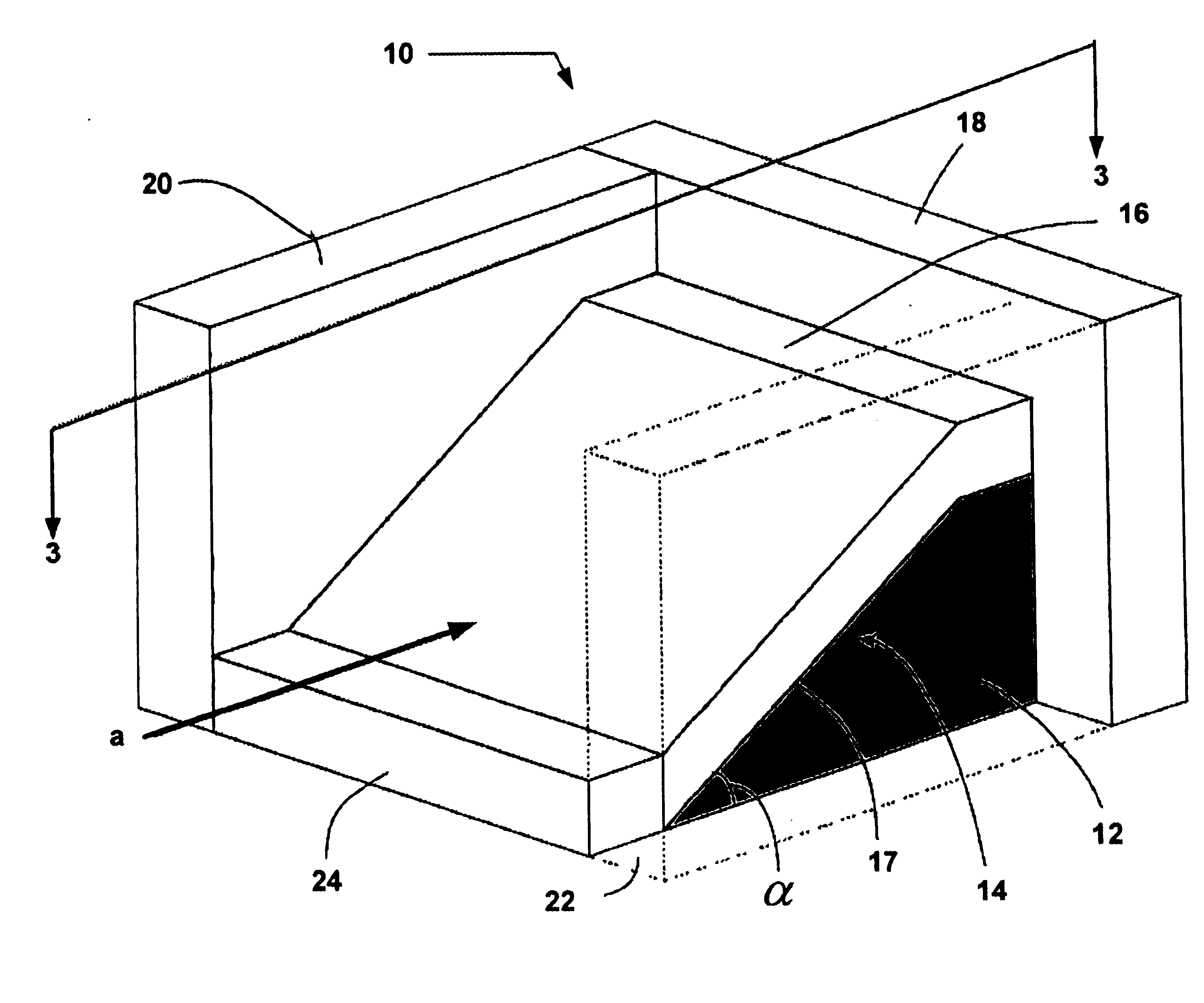
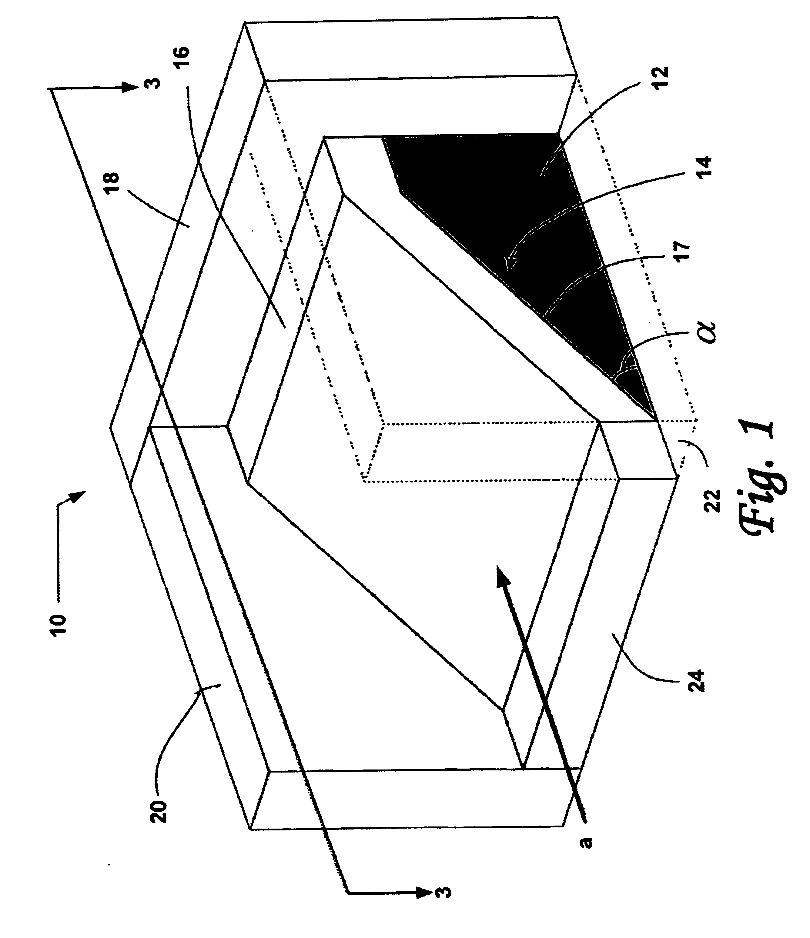
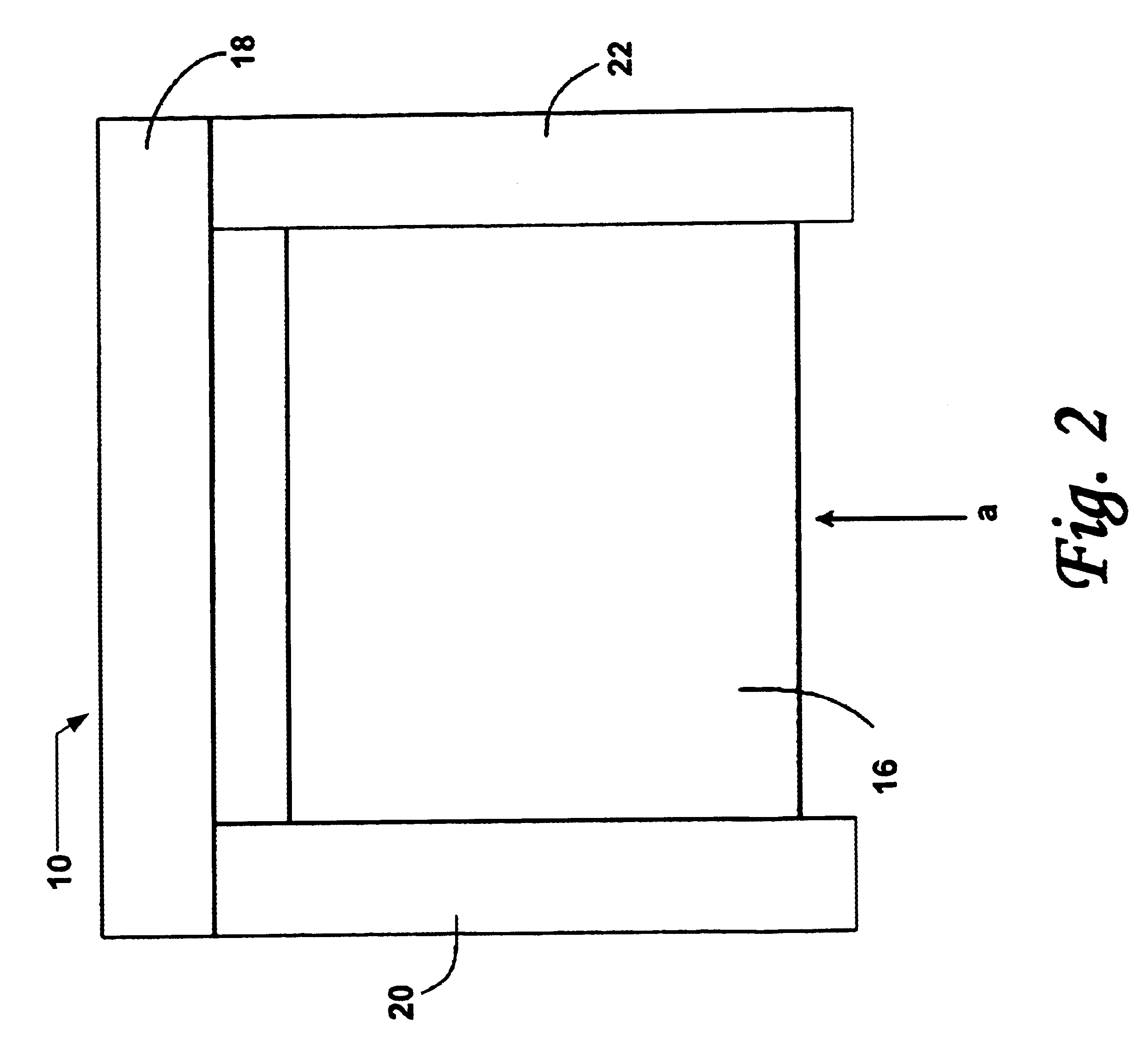
Referring now to the drawings, and specifically to FIGS. 1 through 3, there is shown a bullet trapping backstop 10 for decelerating and trapping projectiles traveling along a line of fire “a” towards backstop 10. (It should be understood that the terms “bullet,”“projectile,” and “round” are used interchangeably herein and refer to projectiles or munitions of any sort or caliber.) Backstop 10 generally includes a foundation or support structure 12 having an upper surface 14 and a projectile trapping medium 16 disposed on upper surface 14. FIG. 2 shows a plan view of upper surface 14 of bullet trapping backstop 10. At least a portion 17 of upper surface 14 is inclined with respect to line of fire “a” by an angle α, which is preferably less than or equal to the angle of repose of projectile trapping medium 16. In embodiments, support structure 12 includes a back wall 18 and opposing first and second sidewalls 20, 22, forming an enclosure around projectile trapping medium 16. (In FIG. 1...


PUM


Abstract

A backstop for decelerating and trapping projectiles generally includes a support structure having an inclined surface and a projectile trapping medium disposed on the inclined surface. The projectile trapping medium may be either a resilient granular ballistic medium or a combination of a ballistic medium with a hydrated super absorbent polymer (SAP) gel. Preferably, the support structure is made of a shock absorbing, foamed, fiber-reinforced concrete, such as SACON®. In embodiments, the support structure also includes an enclosure. Additives may also be mixed into the projectile trapping medium to control alkalinity and prevent leaching of heavy metals.

Description

BACKGROUND OF THE INVENTION1. Field of the InventionThe present invention relates generally to the firing of projectiles on a range, and, more particularly, to an apparatus and method for decelerating and trapping munitions fired on a range.2. Background DescriptionIn order to maintain proficiency in the use of firearms, it is common to engage in target practice on a training range. Traditionally, the primary concern on a training range was the prevention of ricochets. Thus, ranges often use a large dirt berm behind the target to decelerate and trap the bullet.More recently, however, considerable concern has been raised about the environmental impact of heavy metals (e.g., lead, tungsten, copper) contained within the bullet. Though a bullet fired into a mound of dirt is safely contained from the standpoint of no longer being a dangerous projectile, heavy metals within the bullet remain free to leach into the soil, thereby contaminating the environment. Thus, shooting ranges have beg...

Claims


Application Information

Patent Timeline
Patent Type & Authority Patents(United States)
IPC IPC(8): F41J1/00F41J1/12F41J13/00
CPCF41J13/00
Inventor LARSON, STEVEN L.WEISS, CHARLES A.TOM, JOE G.MALONE, PHILIP G.FRANSEN, EDWARD J.
Owner ARMY UNITED STATES GOVERNMENT AS REPRESENTED BY THE SEC OF THE
Why Eureka
Try Eureka