

Detachable connector device
a connector device and detachable technology, applied in the direction of coupling contact members, fixed connections, coupling device connections, etc., can solve the problems of increasing the manufacturing cost of the connector device, the service life of the respective junction terminals is short, and the performance is difficult to adequately exhibit. , to achieve the effect of high frequency properties
- Summary
- Abstract
- Description
- Claims
- Application Information
AI Technical Summary
Benefits of technology
Problems solved by technology
Method used
Image

Examples
second embodiment
Subsequently, an explanation will be given to a connector device according to the invention with reference to FIGS. 7 and 8.
FIG. 7 is across sectional view showing a part of a connector device according to the embodiment, and respective contactors 29 constituting the connector device 28 comprises contact pieces 31 formed to be inclined inwardly of respective through-holes 30 from an outer edge on a surface side of the respective through-holes 30 in the same manner as in the first embodiment. Also, arranged on a contact portion 32 of the respective contact pieces 31 are a plurality of small projections 33 made of a conductive material to project toward an opening on the surface side of the respective through-holes 30.
In addition, the remaining constitution of the embodiment is the same as that of the first embodiment, and so an explanation therefor is omitted.
Subsequently, an explanation will be given to an operation of the second embodiment.
First, when the respective junction termin...
third embodiment
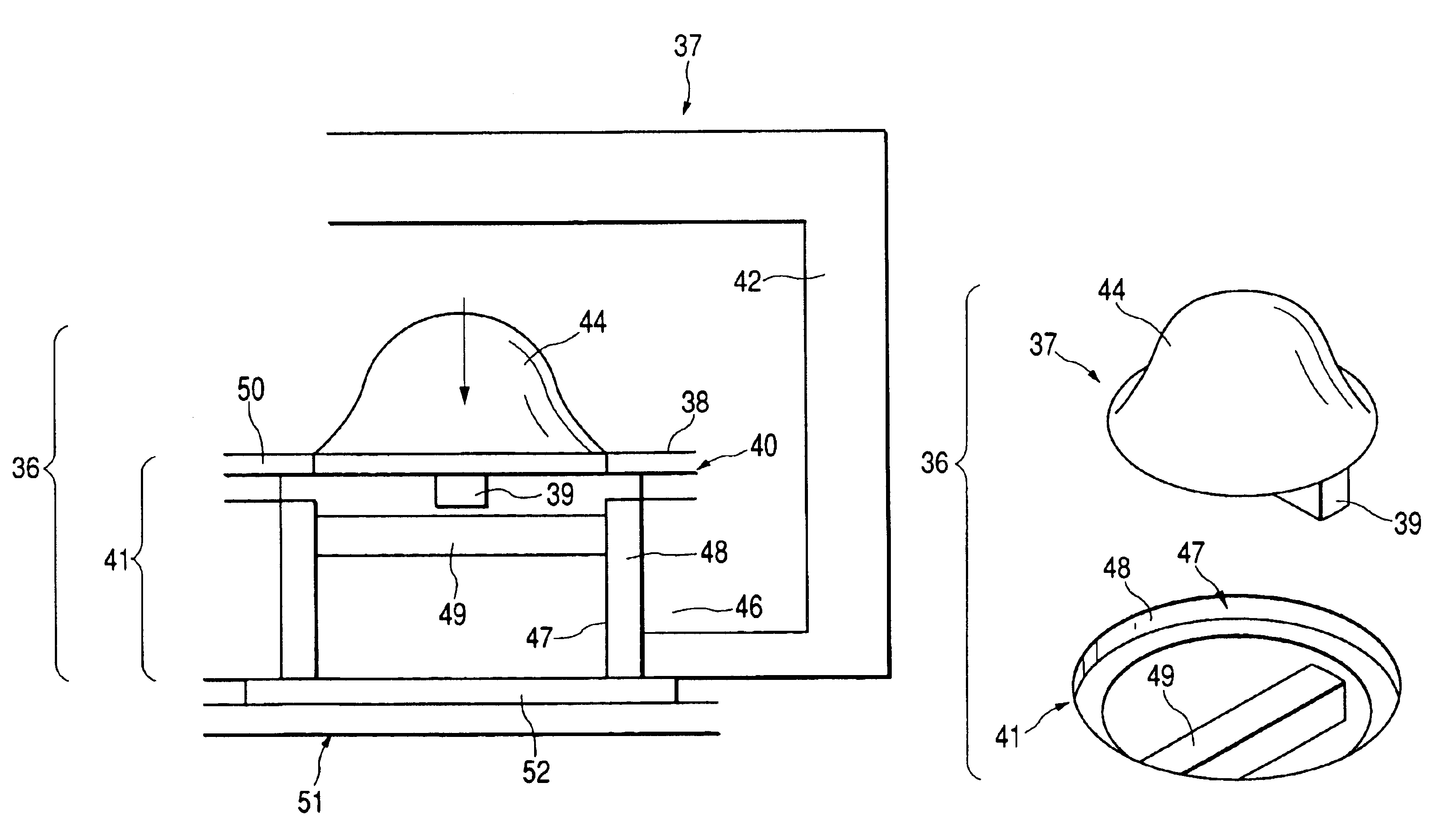
Subsequently, an explanation will be given to a connector device according to the invention with reference to FIGS. 8 and 9.
FIG. 8 is across sectional view showing a part of a connector device according to the embodiment, and FIG. 9 is a perspective view showing the connector device shown in FIG. 8. Also, the embodiment will be described by way of a connector device for connecting a computer device and a computer peripheral device to each other.
As shown in FIG. 8, arranged in a housing 42 of that computer device 37, in which a connector device 36 according to the embodiment is used, is a board 38 having a plurality of junction terminals 39 arranged on a surface thereof, the respective junction terminals 39 being in the form of an elongated rectangular solid and formed to project a small projecting dimension. Also, a plurality of substantially semi-spherical junction terminals 44 are aligned and arranged in positions corresponding to those positions, in which the respective junction ...
PUM
 Abstract
Description
Claims
Application Information