Lead-free solder

a technology of lead-free solder and soldering ring, which is applied in the direction of welding/cutting media/materials, welding apparatus, manufacturing tools, etc., can solve the problems of increased facility cost, human body, environmental pollution, etc., and achieve the effect of low cos

Inactive Publication Date: 2005-01-04
NAT CHENG KUNG UNIV +1
View PDF13 Cites 2 Cited by
  • Summary
  • Abstract
  • Description
  • Claims
  • Application Information

AI Technical Summary

Benefits of technology

One objective of the present invention is to provide a lead-free Sn—Zn-based solder, which has mechanical properties (e.g. tensile strength and elongation) comparable or better than those of a conventional Pb—Sn eutectic alloy, has a low cost, and has a melting point lower than 200° C., or even lower than the melting point of a Pb—Sn eutectic alloy (183.5° C.). Therefore, it will not cause a damage to an IC encapsulation element.

Problems solved by technology

Lead is harmful to a human body and will cause an environmental contamination.
Therefore, such an alloy will cause an increase in the cost of facility.
Furthermore, a high temperature is liable to cause a breakdown on the electric elements.
Some of their melting points are still higher than 200° C. Even though the addition of a large amount of Bi and In can reduce the melting point of the alloy, the cost of the alloy has been dramatically increased.

Method used


Image

  • Lead-free solder
  • Lead-free solder
  • Lead-free solder

Examples


example 1

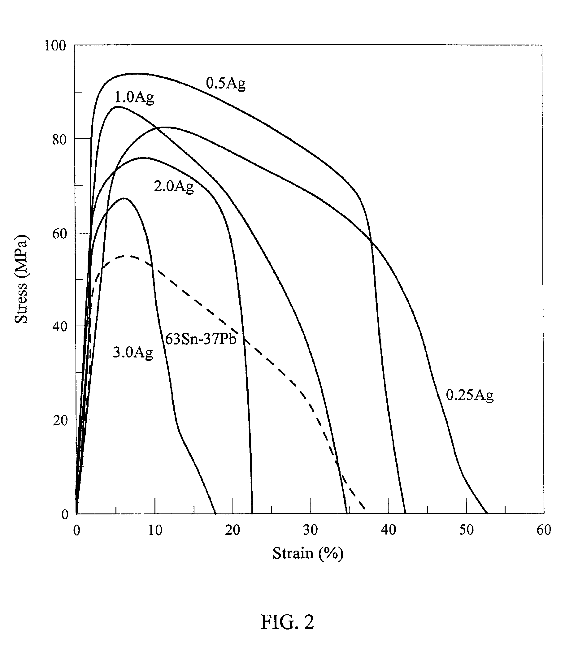
The preparation of the elongation test specimen of a Sn-8.55%Zn-1.0%Ag-zAl series solder alloy and the testing method thereof were the same as the control example. The results indicate that the addition of a small amount of Al (0.01˜0.45 wt %) greatly increases its wetting capability on a Cu based substrate. The experimental results indicate that, when heated to 250° C., the Sn-8.55%Zn-1%Ag-zAl series solder alloy has a wetting capability of about 0.75-1.20 mN under the aid of DMAHCI organic flux. This wetting capability is about one to two times the wetting capability of a Sn-9Zn eutectic solder alloy (˜0.41 mN). Regarding the wetting time, the wetting time of a Sn-8.55% Zn-1% Ag-zAl series solder alloy is about 0.9˜1.1 seconds which is much better than the wetting time of a Sn—Zn eutectic series solder alloy (˜1.32 seconds).

example 2

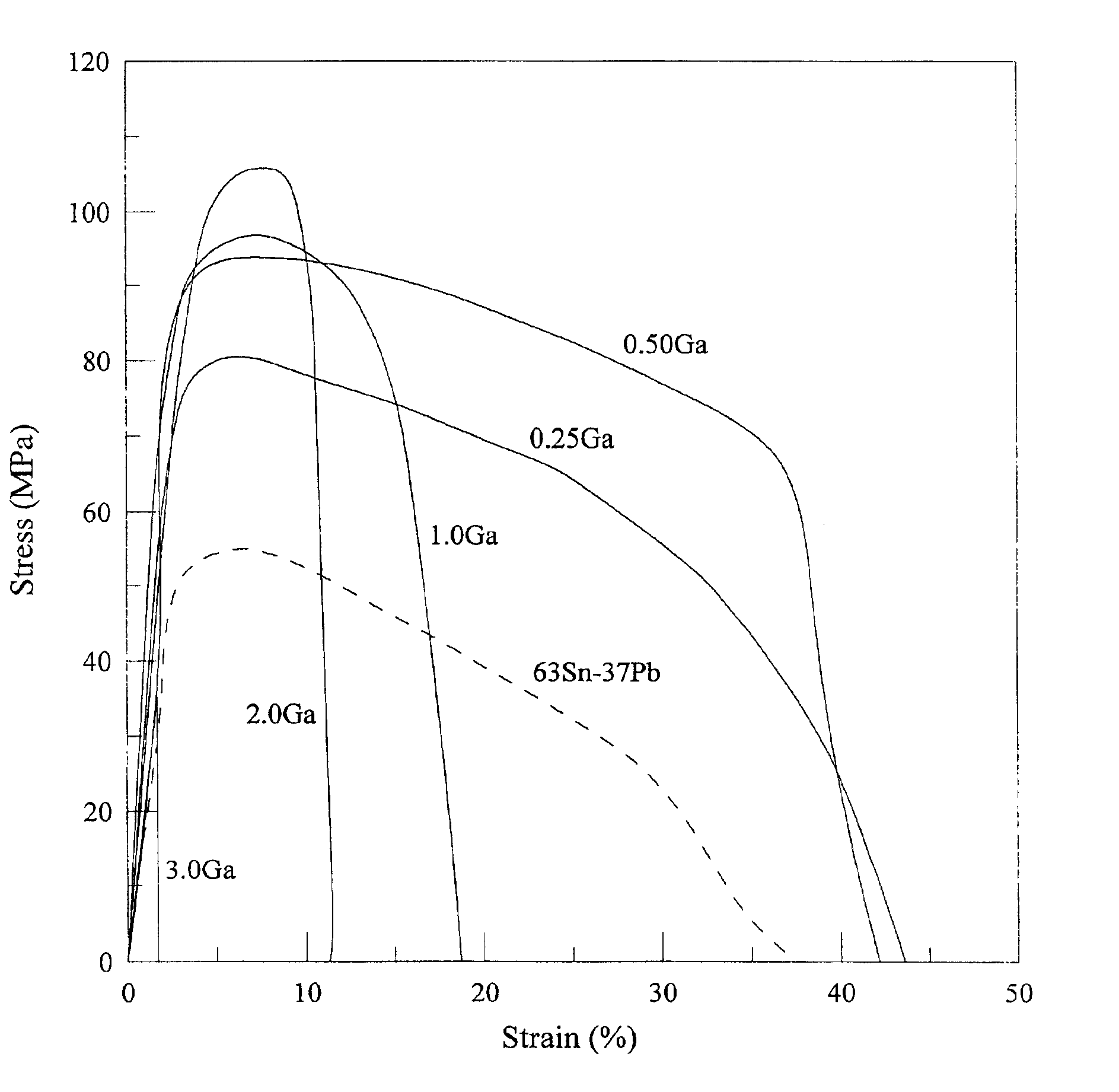
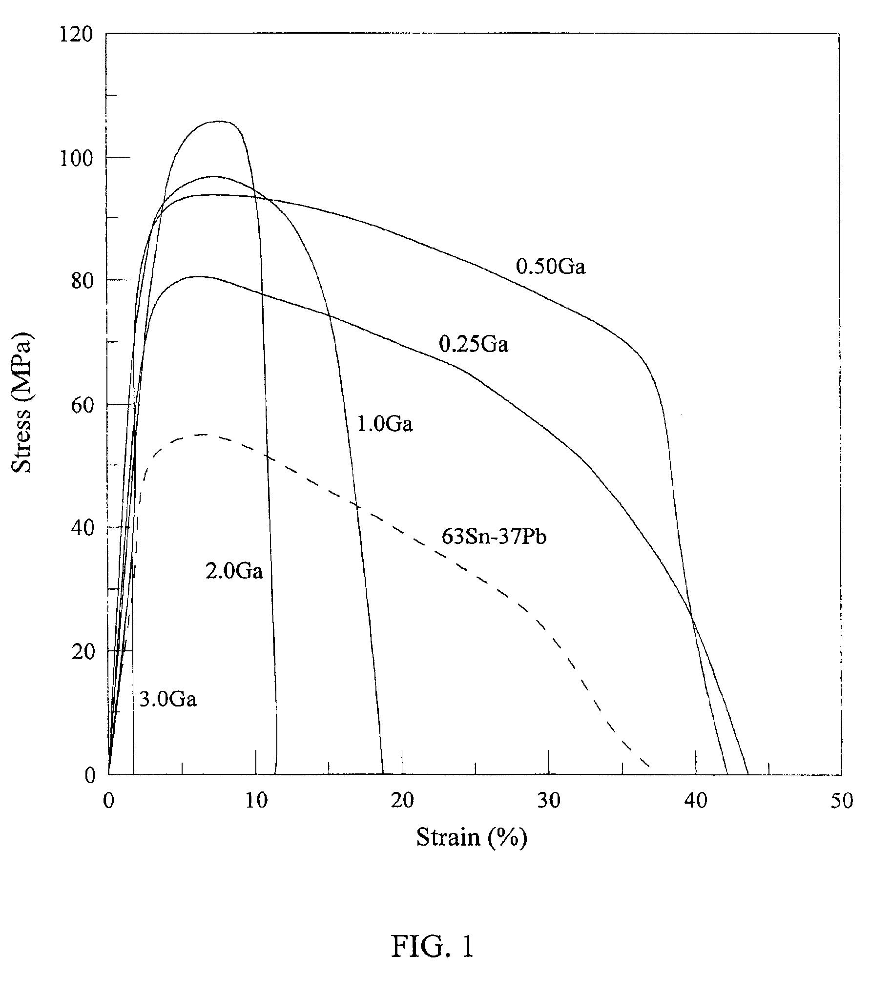
The preparation of the elongation test specimen of a Sn-8.55% Zn-0.45% Al-0.5% Ag-0.25% Ga alloy and the testing method thereof were the same as the control example. The results indicate that: the ultimate tensile strength (UTS) is 80.4 MPa which is about 46% higher than the tensile strength of a 63Sn-37Pb alloy; the elongation is 43.6% which is about 16% higher than the elongation of a 63Sn-37Pb alloy. The melting point of the alloy is 195.55° C. which is very close to the melting point of a 63Sn-37 Pb (183.5° C.).

example 3

The preparation of the elongation test specimen of a Sn-8.55% Zn-0.45% Al-0.5% Ag-0.5% Ga alloy and the testing method thereof were the same as the control example. The results indicate that: the ultimate tensile strength (UTS) is 92.5 MPa which is about 68% higher than the tensile strength of a 63Sn-37Pb alloy; the elongation is 42.2% which is about 12% higher than the elongation of a 63Sn-37Pb alloy. The melting point of the alloy is 194.7° C.

A stress-strain curve of a Sn-8.55Zn-0.45Al-0.5Ag-yGa solder alloy was obtained by repeating the steps of Example 2 and Example 3, as shown in FIG. 1. FIG. 1 also shows the stress-strain curve of a 63Sn-37Pb alloy of the control example.


PUM

PropertyMeasurementUnit
melting pointaaaaaaaaaa

Abstract

This invention discloses a lead-free Sn—Zn—Al—Ag solder alloy, which is composed of 7-10 wt % of Zn, up to 0.5 wt % of Al, up to 4.0 wt % of Ag, and the balance of Sn; and a lead-free Sn—Zn—Al—Ag—Ga solder alloy, which is composed of 7-10 wt % of Zn, up to 0.5 wt % of Al, up to 4.0 wt % of Ag, up to 4.0 wt % of Ga; and the balance of Sn. The lead-free solder alloys of the present invention have better tensile strength and elongation than the conventional Sn—Pb solder alloys. In addition, the lead-free solder alloys of the present invention have a melting point lower than 200° C., which is close to the 183.5° C. of an eutectic Sn—Pb alloy.

Description

FIELD OF THE INVENTIONThe present invention relates to a lead-free solder, particularly a Sn—Zn—Ag—Al tetra-element lead-free solder, and a Sn—Zn—Ag—Al—Ga penta-element lead-free solder.BACKGROUND OF THE INVENTIONAs known by the industry, the main component of a typical solder alloy material is a Pb—Sn alloy. Lead is harmful to a human body and will cause an environmental contamination. Therefore, researches on a lead-free solder material are imperative. A Sn—Ag eutectic alloy has a tensile strength higher than that of a conventional Pb—Sn alloy, but has a high melting point of about 221° C., which is much higher than the melting point (183.5° C.) of a Pb—Sn eutectic alloy. Therefore, such an alloy will cause an increase in the cost of facility. Furthermore, a high temperature is liable to cause a breakdown on the electric elements. Many patents try to reduce the melting point of a Sn—Ag eutectic alloy by adding a small amount of other alloy components, e.g. Cu, Zn, Bi, In and Sb, i...

Claims


Application Information

Patent Timeline
Patent Type & Authority Patents(United States)
IPC IPC(8): B23K35/26C22C13/00
CPCC22C13/00B23K35/262
Inventor LIN, KWANG-LUNGCHEN, KANG-ICHENG, SHOU-CHANGHUANG, JIA-WEI
Owner NAT CHENG KUNG UNIV
Why Eureka
Try Eureka