
Detecting overlapping images in an automatic image segmentation device with the presence of severe bleeding

an automatic image segmentation and image segmentation technology, applied in image data processing, image enhancement, instruments, etc., can solve problems such as numerical effort reduction, and achieve the effect of improving the efficiency of the scanning process

Inactive Publication Date: 2005-01-04
XEROX CORP
View PDF17 Cites 66 Cited by
  • Summary
  • Abstract
  • Description
  • Claims
  • Application Information

AI Technical Summary

Benefits of technology

The techniques described herein enable a user to expediently scan a document or other object, automatically recognizing the shape of the document within the digitized image, and composing a digital document incorporating the object.
The techniques described above are advantageous because they improve the efficiency of a scanning process, in the presence of severe bleeding.

Problems solved by technology

The authors further describe a technique for describing the primitives using moments in a normalized manner; resulting in a decrease in the numerical effort.

Method used


Image

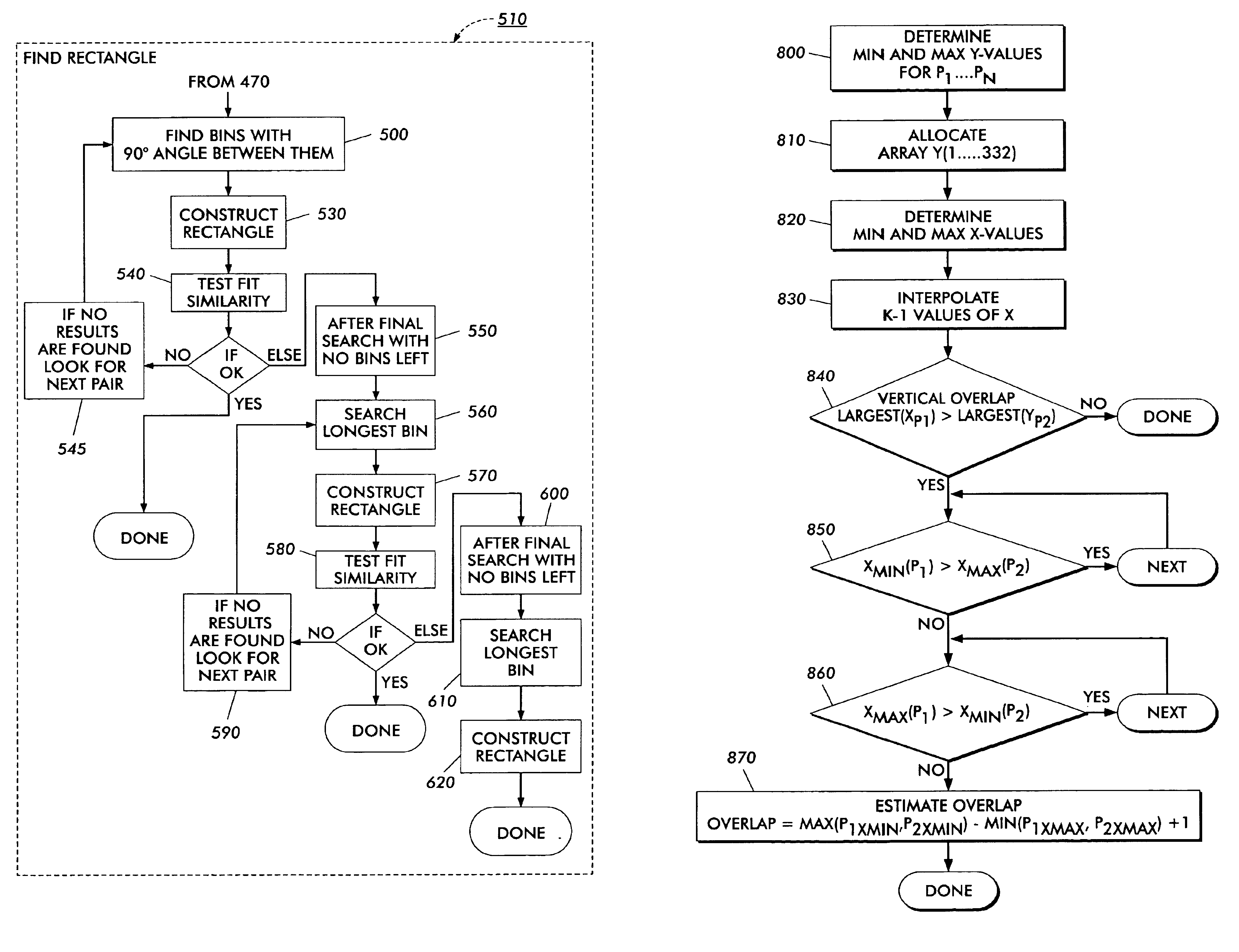
  • Detecting overlapping images in an automatic image segmentation device with the presence of severe bleeding
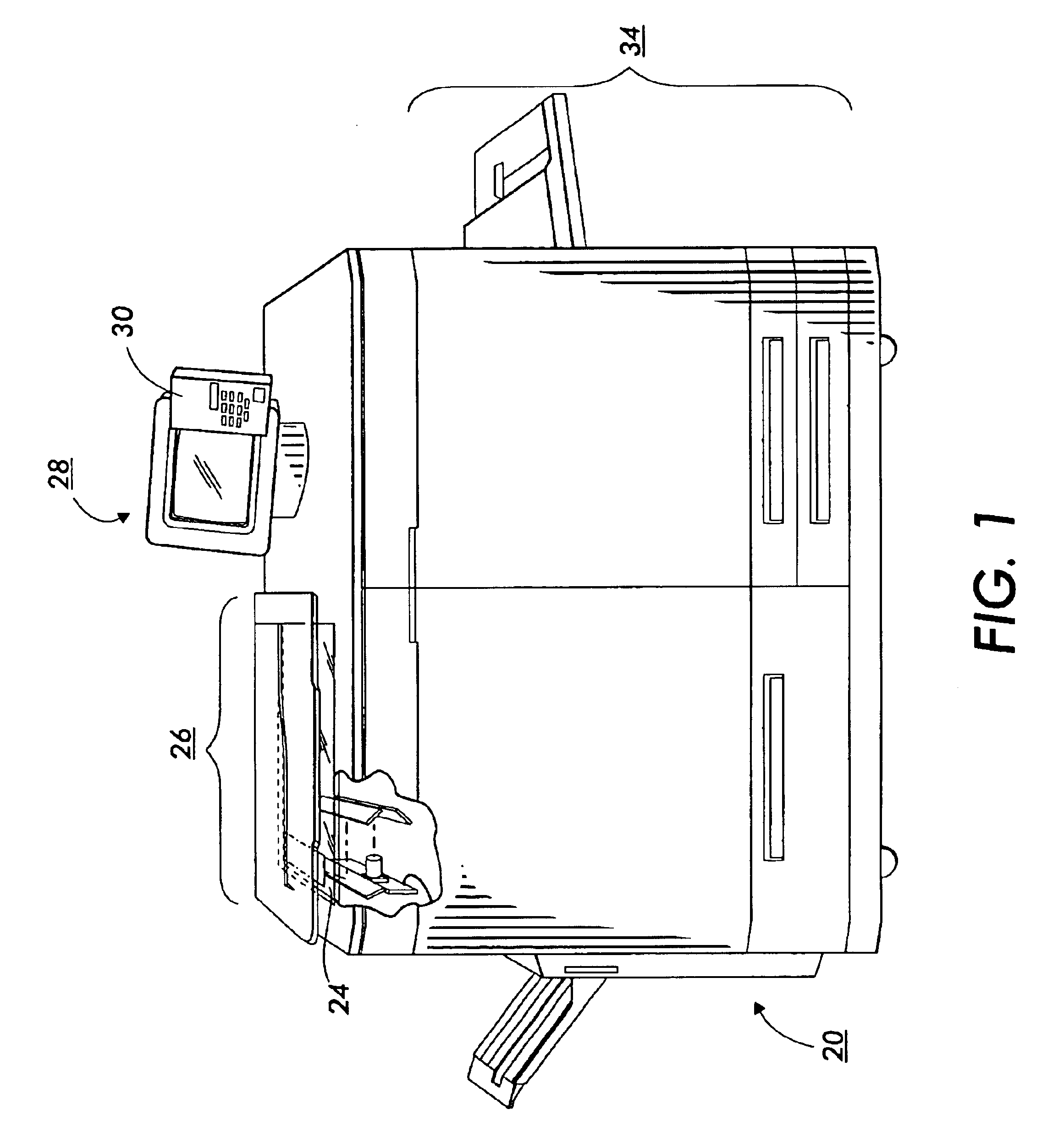
  • Detecting overlapping images in an automatic image segmentation device with the presence of severe bleeding
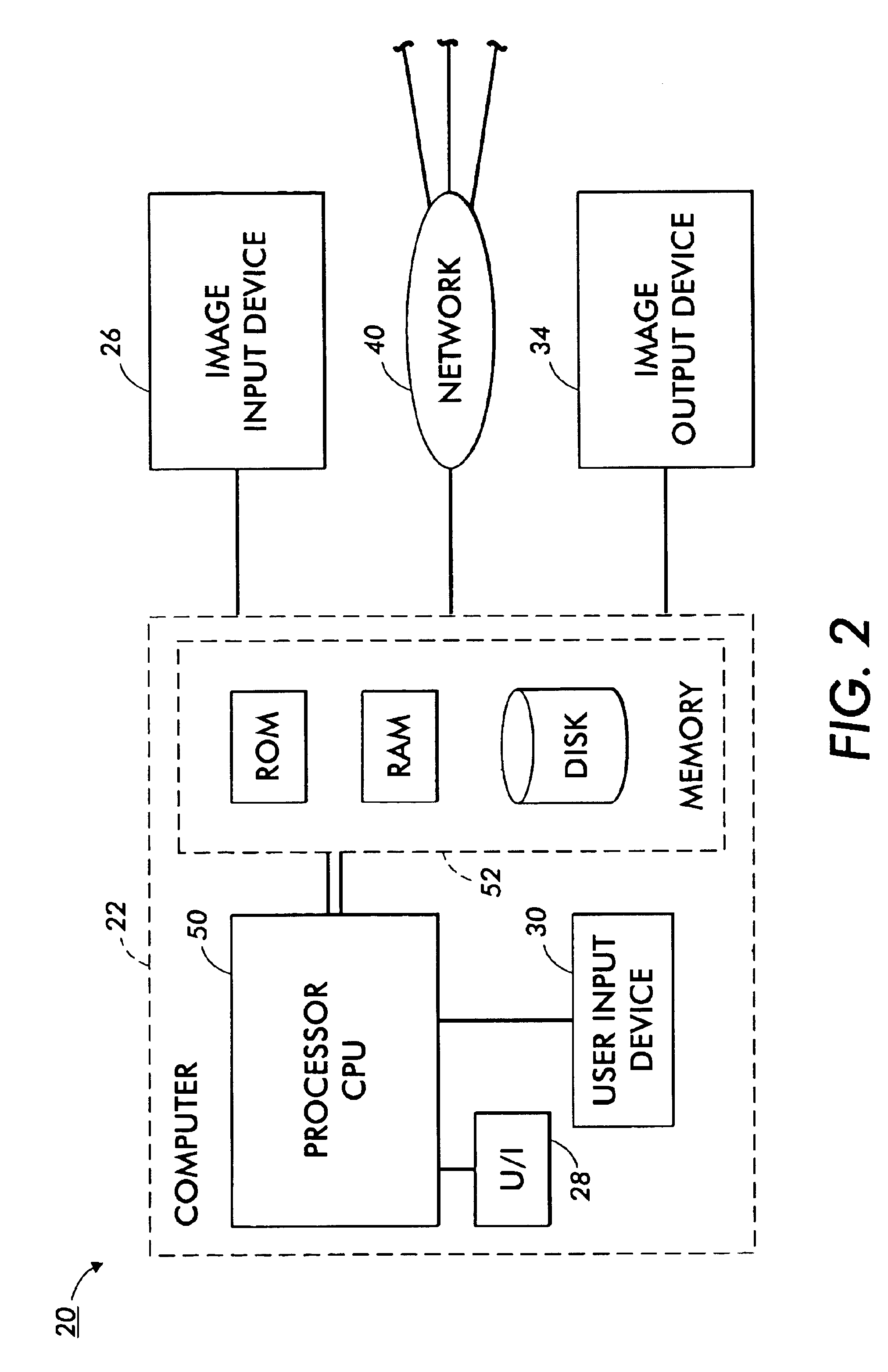
  • Detecting overlapping images in an automatic image segmentation device with the presence of severe bleeding

Examples


Embodiment Construction

For a general understanding of the present invention, reference is made to the drawings. In the drawings, like reference numerals have been used throughout to designate identical elements. In describing the present invention, the following term(s) have been used in the description.

The term “data” refers herein to physical signals that indicate or include information. When an item of data can indicate one of a number of possible alternatives, the item of data has one of a number of “values.” For example, a binary item of data, also referred to as a “bit,” has one of two values, interchangeably referred to as “1” and “0” or “ON” and “OFF” or “high” and “low.” A bit is an “inverse” of another bit if the two bits have different values. An N-bit item of data has one of 2N values. A “multi-bit” item of data is an item of data that includes more than one bit.

“Memory circuitry” or “memory” is any circuitry that can store data, and may include local and remote memory and input / output devices...


PUM


Abstract

A method for processing multiple digital images using an imaging input device so as to reduce bleeding of edges of the multiple digital images by determining the boundaries of each of the digital images, including detecting a boundary of a first image; detecting a boundary of a second image; determining an overlap between the detected boundaries of the first image and second images; calculating the overlap between the first and second images and modeling a third image from the calculated overlap of the first and second images wherein the third image contains at least said first and second images and represents a depiction of said first and second images without an overlap between said first and second images.

Description

This invention relates generally to detection of a particular images of several documents placed on the platen of an image input device in the presence of severe background bleeding, and more particularly to the automatic detection of the overlap of a series of images placed on the platen using the technologies of joining orphaned images, linear regression algorithms and collinearity detectors.Cross reference is made to the following related applications are hereby incorporated by reference for their teachings:“METHOD AND APPARATUS FOR IDENTIFYING A PLURALITY OF SUB-IMAGES IN AN INPUT IMAGE,” Dennis L. Venable et al., application Ser. No. 08 / 788,538, filed Jan. 21st, 1997;“STRUCTURED IMAGE (SI) EDITOR AND METHOD FOR EDITING STRUCTURED IMAGES,” Michael R. Campanelli et al., U.S. Pat. No. 5,666,503; and“LOCATING THE POSITION AND ORIENTATION OF MULTIPLE OBJECTS WITH A SMART PLATEN,” Dennis L. Venable., U.S. Pat. No. 6,738,154.“AUTOMATIC IMAGE SEGMENTATION IN THE PRESENCE OF SEVERE BACK...

Claims


Application Information

Patent Timeline
Patent Type & Authority Patents(United States)
IPC IPC(8): G06T5/00G06T7/60G06V10/25G06T1/00G06V10/44H04N1/04H04N1/40
CPCG06T7/0083G06K9/4604G06K9/3233G06T2207/10008G06T2207/30176G06T2207/20192G06T7/12G06V10/25G06V10/44
Inventor VENABLE, DENNIS L.
Owner XEROX CORP
Learn More