Wide view-field three-D CT imaging method

A technology of CT imaging and large field of view, applied in the field of X-ray CT, can solve the problem of small scanning field of view

Inactive Publication Date: 2006-11-22
BEIHANG UNIV
View PDF0 Cites 28 Cited by
  • Summary
  • Abstract
  • Description
  • Claims
  • Application Information

AI Technical Summary

Problems solved by technology

[0005] The technical solution of the present invention is to provide a three-dimensional CT imaging with a large field of view based on two offset scans of the inspection table for the problem of a small scanning field of view in the current three-dimensional CT based on single circular orbit cone beam scanning and FDK reconstruction algorithm method, to solve the fast three-dimensional tomography of larger-sized components and the high-magnification ratio micro-tomography of small specimens. Through two single-circle-orbit cone-beam scanning and quasi-parallel-beam rearrangement processing on the inspection table, the single-circle-orbit cone-beam The scanning imaging field of view is expanded to 3 times of the original, and the scanning and reconstruction process is simple and efficient

Method used


Image

  • Wide view-field three-D CT imaging method
  • Wide view-field three-D CT imaging method
  • Wide view-field three-D CT imaging method

Examples


Embodiment Construction

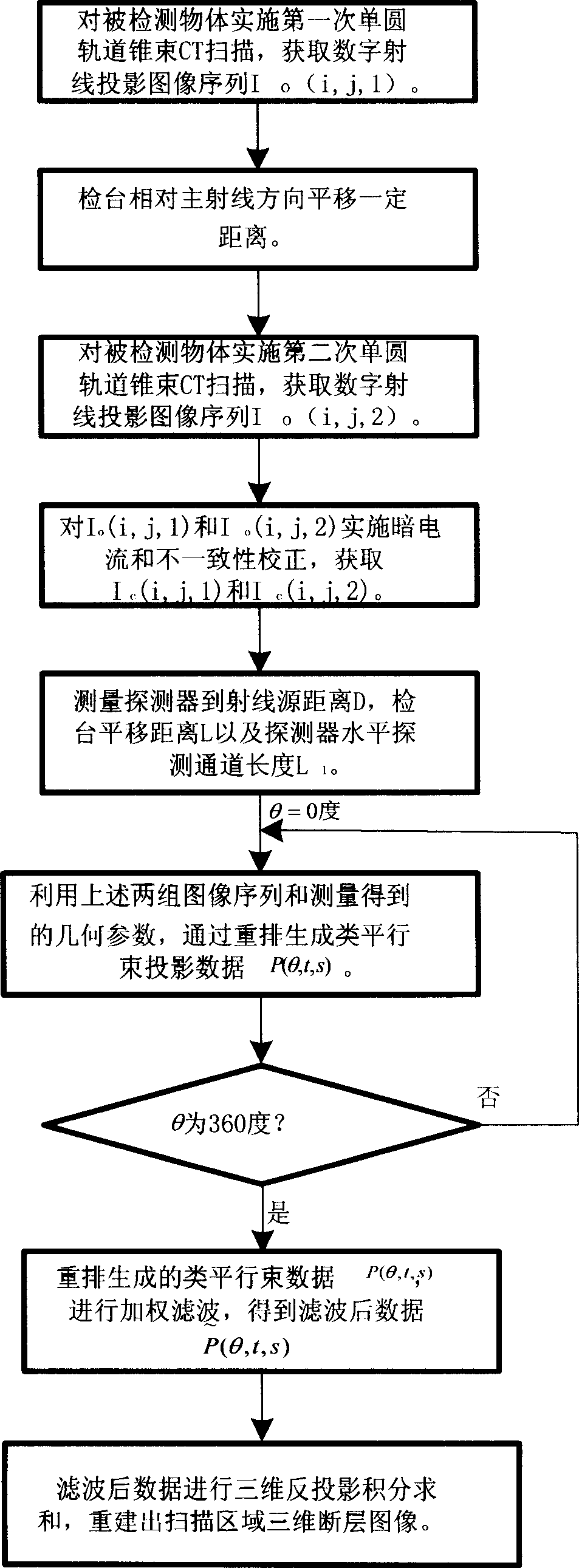
[0040] like figure 1 , the specific implementation steps of the present invention are as follows:

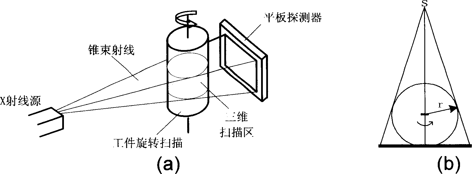
[0041] (1) Place the object to be scanned on the rotating inspection table of the cone beam CT scanning system to ensure that the rotation center of the inspection table is located on the main ray;

[0042](2) Transilluminate the object with the collimated cone beam rays. At the same time, the inspection table rotates continuously at a constant speed, and the area array detector continuously collects the ray projections transmitted through the object at a fixed sampling speed to obtain the first set of two dimensional digital image sequence;

[0043] (3) When the inspection table rotates 360 degrees, the area array detector stops sampling, and the inspection table and the radiation source stop at the same time, that is, the first single circular orbit cone beam CT scan is completed;

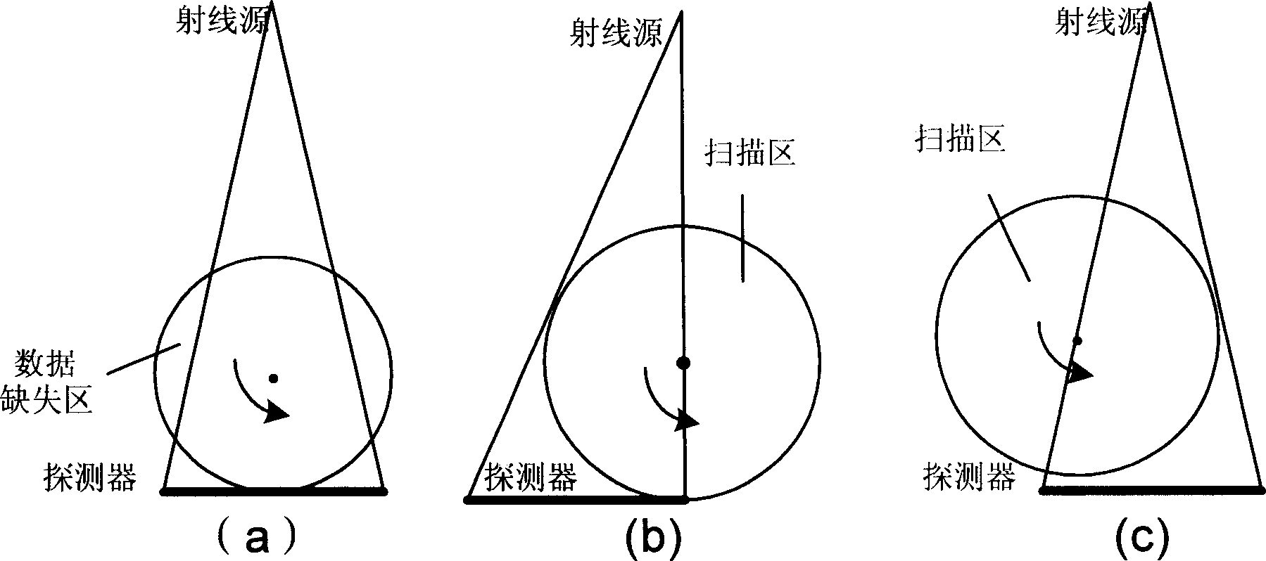
[0044] (4) The inspection table carrying the object is translated a certain distance perpend...


PUM


Abstract

The 3D CT imaging method for large view field comprises: (1) taking first single-circular orbit cone-beam CT scanning to obtain the first digital ray projection image sequence; (2) removing the platform vertical the main ray with some distance to take the second CT scanning and obtain the second image sequence; (3) correcting former two images for dark current and inconsistency; (4) recording distance from ray source to detector, former moved distance and detector level channel number; (5) with the projection rearrangement algorithm in this invention, rearranging former two images into self-contained quasi-parallel image sequence; (6) with the quasi-parallel ray reconstructing algorithm in this invention, reconstructing the 3D CT image. This invention can enlarge the view area more than 3 times with high efficiency.

Description

technical field [0001] The invention relates to a three-dimensional CT imaging method with a large field of view, belonging to the technical field of X-ray CT. Background technique [0002] In the X-ray CT system, the X-ray source emits X-rays, which pass through a certain area of ​​the detected object from different angles, and the detector placed opposite the ray source receives them at corresponding angles, and then attenuates the rays according to different degrees at each angle. Using a certain reconstruction algorithm and computer calculations, the ray attenuation coefficient distribution mapping image of the scanned area of ​​​​the object is reconstructed, so that the image can be reconstructed by projection, and the characteristics of the medium density, composition, and structural shape of the object in the area can be reproduced without loss. . [0003] In the existing typical cone-beam ray 3D-CT imaging, in order to meet the complete data conditions of Tuy, Smith...

Claims


Application Information

Patent Timeline
Patent Type & Authority Applications(China)
IPC IPC(8): G01N23/04A61B6/03
Inventor 傅健魏东波姜明卿磊孙晶晶龚磊黄琼
Owner BEIHANG UNIV
Why Eureka
Try Eureka