Fireworks device

a firework and device technology, applied in the direction of fireworks, lighting and heating apparatus, weapons, etc., can solve the problems of not necessarily igniting all stars, affecting the use of fireworks, and a major fire risk of fireworks during us

Inactive Publication Date: 2005-01-11
JAKOB HATTELAND KJEMI
View PDF14 Cites 15 Cited by
  • Summary
  • Abstract
  • Description
  • Claims
  • Application Information

AI Technical Summary

Benefits of technology

These objects are achieved by a fireworks device, comprising a number of light effect devices and a drive device arranged to drive the light effect devices apart, characterized in that each light effect device comprises at least one electrical / electronic light source, an energy-storage device and a control device for controlling the light sources.

Problems solved by technology

Amongst other things, the fireworks represent a major fire risk during use, since the falling stars burn at high temperatures and can set fire to objects on the ground or objects they meet on their way to the ground.
The stars also constitute an explosion and fire risk during production, storage, transport and handling immediately preceding launching and use.
Furthermore, there is the risk that all the stars are not necessarily ignited when the booster charge is fired.
This results in stars which are not ignited falling to the ground, and these objects constitute a fire and explosion risk for the future, which can be particularly dangerous in the hands of children.
These undetonated remains also represent pollution of the environment, since the chemical substances in the stars can be poisonous or environmentally harmful in other ways.
Correctly ignited stars also produce pollution of the area on the ground, as the star's core may contain harmful substances which are not burned, particularly when the core contains lead.
Additional problems are represented by discharges into the air during combustion of the stars.
The smoke which is created during combustion is not only environmentally harmful, but is also detrimental to the visual effect of the fireworks.
The formation of smoke causes the light effects from the firework and from other fireworks in the vicinity to be dimmed and obscured.
The above-mentioned factors involving fire hazard and damage to the environment have resulted in the prohibition of the use of fireworks in a number of places, including city centres.
Traditional fireworks, moreover, occupy a relatively large amount of space, thus entailing high transport and storage costs.
A final problem with to-day's pyrotechnic firework stars is the risks involved in handling the chemical substances in the work environment during production of the stars.

Method used


Image

  • Fireworks device
  • Fireworks device

Examples


Embodiment Construction

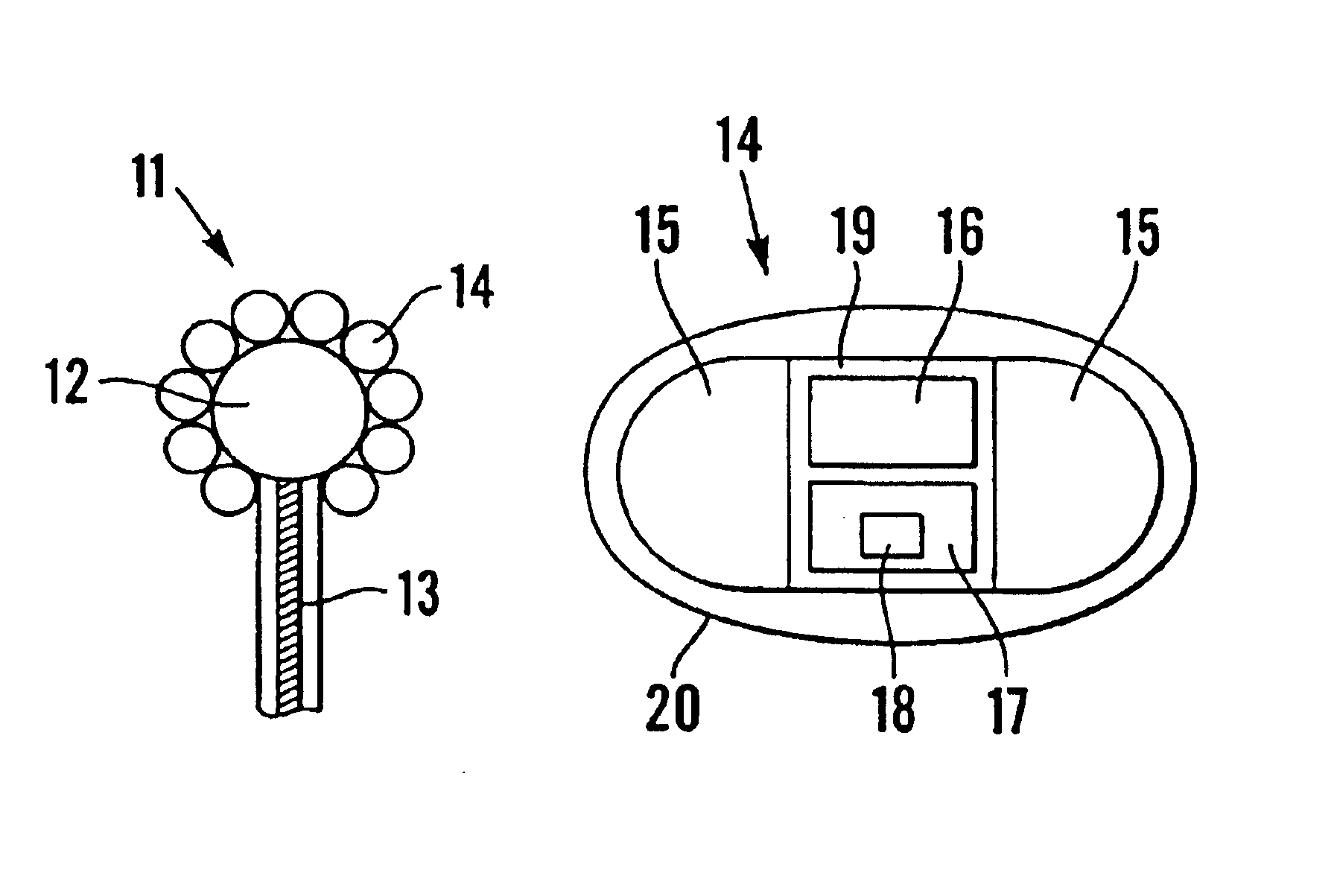
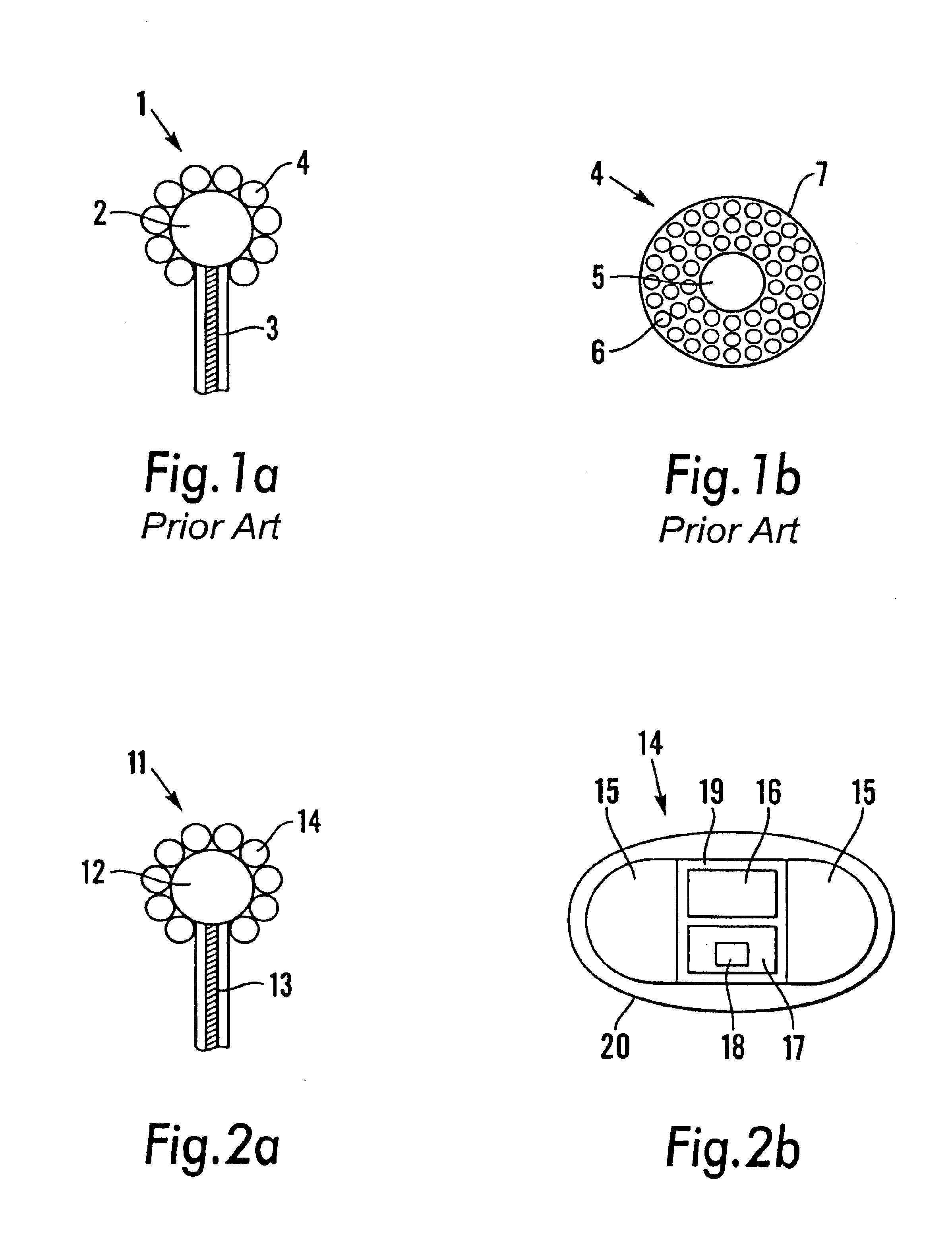
In FIG. 1a an illustration is given of how a fireworks device, or more specifically a fireworks projectile, can be constructed according to the prior art. The projectile 1 consists of a booster charge 2, a fuse 3 and a number of firework stars 4. When it is used the projectile 1 is fired into the air by a lifting charge (not illustrated). The lifting charge may be installed in and accompany the firework, if the firework is of the rocket type, or the lifting charge may be installed in a launching device on the ground. In both cases the fuse 3 is lit during launching, and after a period of time, which is determined by the fuse's burning time, the booster charge 2 is fired. This firing causes preferably all the stars 4 to be ignited, and they are scattered at an exit velocity and direction before falling to the ground.

FIG. 1b is a principle illustration of the construction of a traditional pyrotechnic firework star. The star 4 consists of a core 5 of glass or metal, e.g. lead or iron. ...


PUM


Abstract

A fireworks device, including a number of light effect devices as a replacement for traditional pyrotechnic stars. Each light effect device includes electrical/electronic light sources, preferably high-intensity light-emitting diodes, an energy-storage device and a control device. The light effect device for use in such a fireworks device can be used together with a fireworks system, a fireworks rocket and a ground firework in which the firework device is included.

Description

BACKGROUND OF THE INVENTIONThe invention relates to a fireworks device, and especially a fireworks device wherein pyrotechnic stars are replaced by electrical / electronic light effect devices.The invention also relates to a light effect device for use in fireworks, a fireworks system and a fireworks rocket in which the fireworks device is included.Pyrotechnics is a field with traditions going back for many centuries. Even though technical developments have tended to produce more impressive, more precise, safer and to some extent more environmentally friendly fireworks, the basic principles are the same as in earlier times. Traditional fireworks, particularly aerial fireworks, comprise a pyrotechnic projectile which is fired into the air by means of a first charge, called the lifting charge, whereupon it is exploded by a second charge, called the booster charge. When the booster charge is fired; a number of pyrotechnic light effect devices, usually described as fireworks stars, are no...

Claims


Application Information

Patent Timeline
Patent Type & Authority Patents(United States)
IPC IPC(8): G09F13/00G09F13/46F21K99/00F42B4/04F42B4/00
CPCG09F13/46F42B4/04
Inventor HATTELAND, JAKOB
Owner JAKOB HATTELAND KJEMI
Why Eureka
Try Eureka