Electric power tool

a technology of electric power tools and tools, applied in the direction of manufacturing tools, power tools, portable power tools, etc., can solve the problems of battery pack disengagement, inconvenience for carrying electric power tools, etc., and achieve the effect of reducing the size of reducing the dimensional difference between the tool unit and the battery pack, and strengthening the cohesive effect between the two

Inactive Publication Date: 2005-01-11
MOBILETRON ELECTRONICS
View PDF10 Cites 97 Cited by
  • Summary
  • Abstract
  • Description
  • Claims
  • Application Information

AI Technical Summary

Benefits of technology

The secondary objective of the present invention is to provide an electric power tool, in which the size of a battery pack thereof and a tool unit thereof are effectively reduced.
The foregoing objectives of the present invention are attained by the electric power tool, which is composed of a tool unit and a battery pack. The tool unit includes a pair of conjunct grooves and two corresponding blocks. The battery pack includes a pair of conjunct rails and two locking members. The tool unit and the battery pack are connected and locked with each other respectively by that the conjunct grooves and the conjunct rails are interconnected with each other and the two locking members and the two blocks are jammed together. In addition, the tool unit and the battery pack can be dimensionally reduced and the cohesive effect therebetween can be strengthened respectively by the conjunct grooves and the conjunct rails.

Problems solved by technology

Hence, the battery pack and the tool unit will structurally and dimensionally enlarged to cause inconvenience for carrying the electric power tool.
Additionally, when the battery pack is connected with the tool unit, the pawl is directly burdened with the whole weight of the battery pack to easily damage the pawl or the block while the battery pack is slightly impacted to further cause the battery pack to disengage from the tool unit; this aforementioned drawback can be found in U.S. Pat. No. 5,799,739.

Method used


Image

  • Electric power tool
  • Electric power tool
  • Electric power tool

Examples


Embodiment Construction

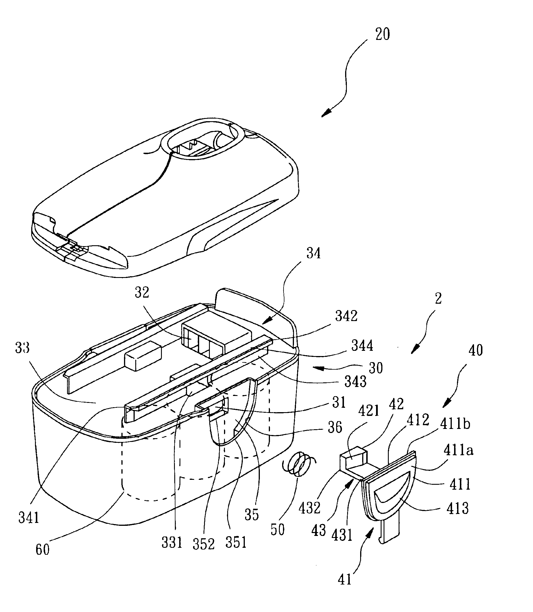
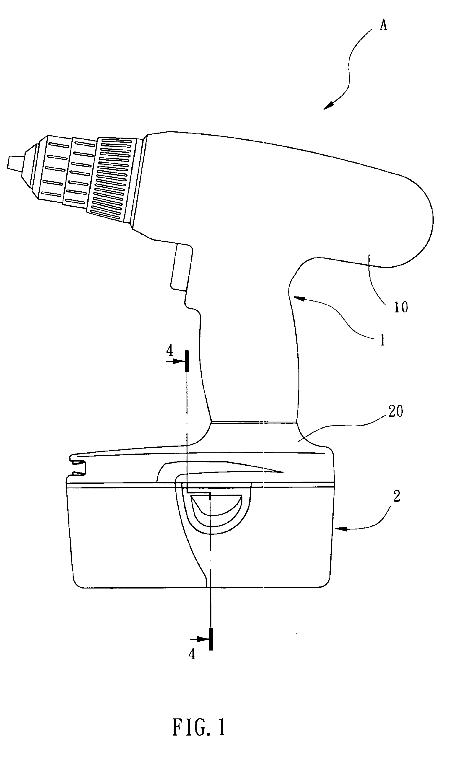
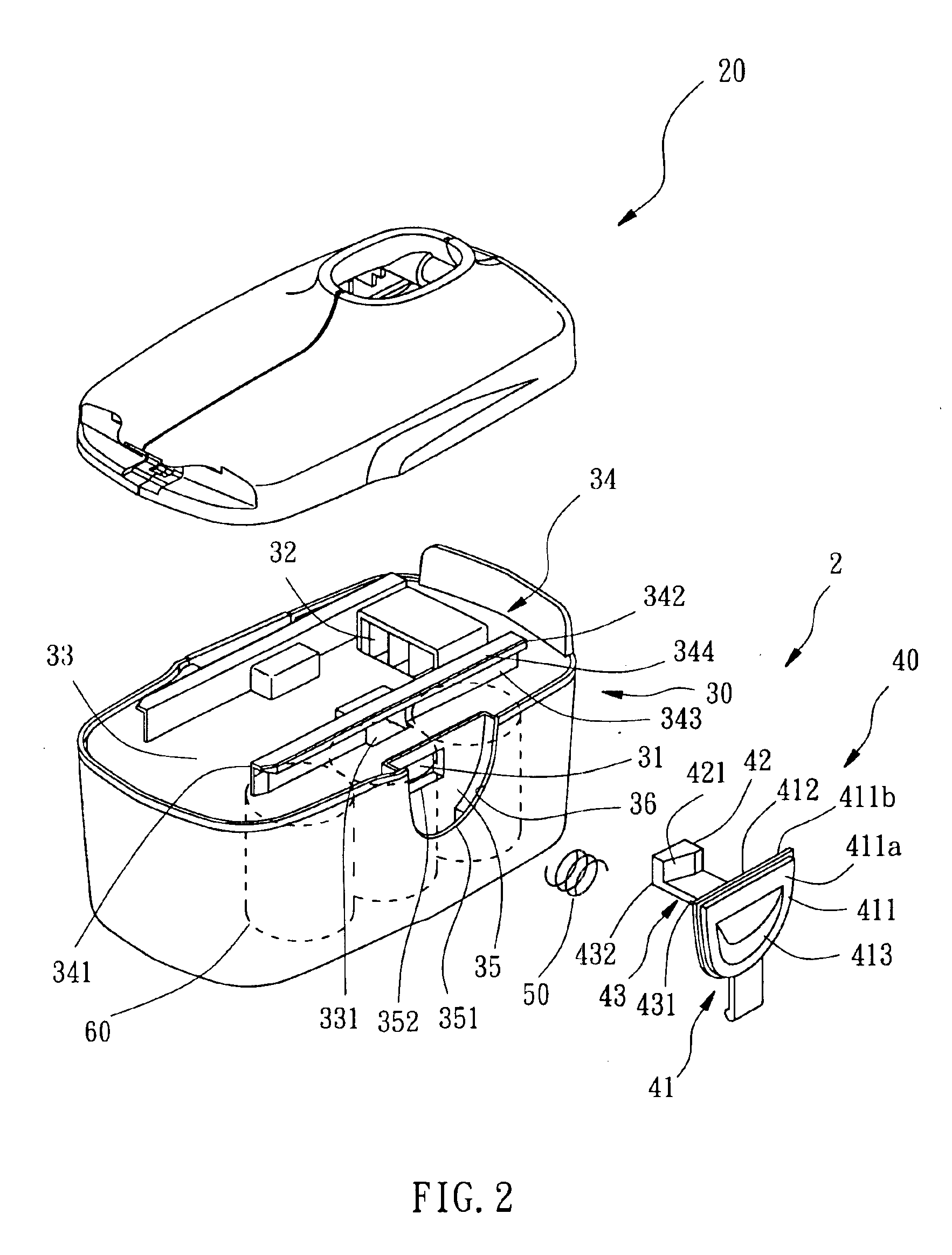
Referring to FIGS. 1-3, an electric power tool A constructed according to a preferred embodiment of the present invention is composed of a tool unit 1 and a battery pack 2.

The tool unit 1 includes a tool body 10 and a coupling member 20 connected to a bottom side of the tool body 10, wherein the tool body 10 is well known to the one who is skilled in the art, such that no more description of the tool body 10 is required. A receiving chamber 21 is formed inside the coupling member 20 and defines a bottom opening 211 and a lateral opening 212 respectively at a bottom side and a lateral side of the coupling member 20, wherein the bottom opening 211 and the lateral opening 212 communicate with each other. The coupling member 20 has a pair of parallel skeleton-like members 22 positioned at bilateral sides of the chamber 21 and extending respectively from an end thereof in proximity of the lateral opening 212 towards the other end thereof. Each of the two skeleton-like members 22 has a co...


PUM


Abstract

An electric power tool includes a tool unit and a battery pack. The tool unit includes a pair of conjunct grooves and two corresponding blocks. The battery pack includes a pair of conjunct rails and two locking members. The tool unit and the battery pack are connected and locked with each other respectively by that the conjunct grooves and the conjunct rails are interconnected with each other and the two locking members and the two blocks are jammed together. In addition, the tool unit and the battery pack can be dimensionally reduced and the cohesive effect therebetween can be strengthened respectively by the conjunct grooves and the conjunct rails.

Description

BACKGROUND OF THE INVENTION1. Field of the InventionThe present invention relates generally to electric power tools, and more particularly, to a direct-current electric power tool.2. Description of the Related ArtThe power source of a general electric power tool can be alternate current and direct current provided by a battery pack, wherein the latter is more popular than the former with common amateur users.A commercially available direct-current power tool, such as U.S. Pat. Nos. 5,799,739 and 5,902,080, is primarily composed of a tool unit and a battery pack. The tool unit includes a coupling receptacle having a receiving chamber formed therein, an opening in communication with the receiving chamber, and an electrical contact disposed inside the chamber. The battery pack includes a connector protruded outwards and an electrical output contact. The connector of the battery pack is inserted into the chamber to enable the electrical output contact to electrically connect the electri...

Claims


Application Information

Patent Timeline
Patent Type & Authority Patents(United States)
IPC IPC(8): B25F5/00B25F5/02
CPCB25F5/02
Inventor WU, CHIEN-CHUN
Owner MOBILETRON ELECTRONICS
Why Eureka
Try Eureka