Rotary damper device

a damper device and rotary technology, applied in the direction of shock absorbers, manufacturing tools, wing accessories, etc., can solve the problems of inability to solve the problem affecting the operation of the check valve, and the toilet seat may collide with the toilet stool bowl, etc., to achieve the effect of preventing a slip angle (backlash), quick operation of braking or damper function, and simple constitution

Inactive Publication Date: 2005-01-11
SANKYO SEIKI MFG CO LTD
View PDF23 Cites 33 Cited by
  • Summary
  • Abstract
  • Description
  • Claims
  • Application Information

AI Technical Summary

Benefits of technology

It is an advantage of the present invention to provide a rotary damper device capable of preventing a slip angle (backlash) and quickly operating a braking or damper function with a simple constitution at a low cost.
In accordance with an embodiment of the present invention, a damper device may include a case in which a viscous fluid is filled and sealed, a rotation shaft rotatably supported by the case, a rotation vane formed protruded from the rotation shaft and a check valve mounted on the tip part of the rotation vane, wherein a passage where the viscous fluid passes through is formed in the rotation vane, the check valve is provided with an opposing face part facing the passage and a frame body interposing the rotation vane, and an elastic member for energizing so that the opposing face part of the check valve closes the passage of the rotation vane formed in either of the rotation vane or the opposite bide of the frame body of the opposing face part.
As a result, with a simple constitution, when the rotation shaft is rotated in a damper operating direction, the opposing face part of the check valve closes the passage of the fluid in the rotation vane and, when the rotation shaft is turned in the opposite direction, in other words, in a slipping direction, the opposing face part of the check valve opens the passage of the fluid by the flowing pressure of the viscous fluid.
In the present invention, when the elastic member is integrally formed with the frame body of the check valve opposite the opposing face part so as to abut the rotation vane, the constitution can be further simplified.
Preferably, the elastic member is integrally formed with the frame body by using a synthetic resin with oil resistance and wear resistance, and may be formed in a feeler shape, a T-shape, an arch-shape, a truncated chevron shape, or the like.
Preferably, a regulating part is formed between the rotation vane and the opposite side of the frame body to the opposing face part for restricting the amount of elastic deformation of the elastic member. When the regulating part is provided, the elastic member is elastically doformed within the predetermined range of elasticity and thus a stable operation can be performed for a long period.

Problems solved by technology

However, check valves in the prior-art have various problems that need to be solved.
This period causes a slip angle that does not work as a damper function for the rotor shaft.
In the case of the slip angle being large, when a toilet seat is opened halfway and released, the toilet seat may collide with the toilet stool bowl.
Also, the large slip angle causes variations in angle when the toilet seat is braked.
A damper device without a backlash, is complicated and requires a lot of components.
Also, a rotary damper is a damper in which the slip angle is reduced by using a spring, hut many components are required and its assembling workability is not satisfactory.
However, with this device, the elastic deformation part is formed in the portion to which a high pressure of viscous fluid is applied causes a problem of its durability.

Method used


Image

  • Rotary damper device
  • Rotary damper device
  • Rotary damper device

Examples


first embodiment

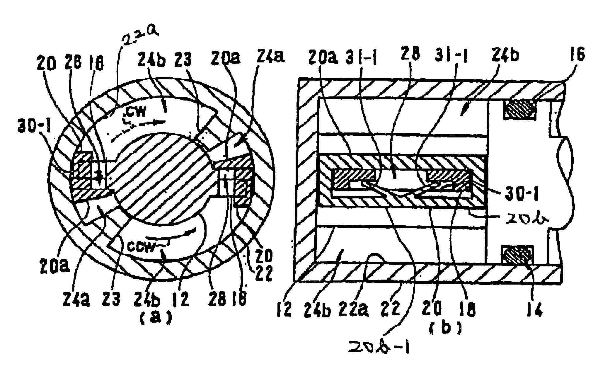
The elastic protrusion parts 30-1 are formed in a V-shaped leg section 31-1 as a first embodiment and so constituted that the end parts are abutted and pushed against the wall face of the rotation vane 18 even at a stopping state. Therefore, at a stopping state when a rotating operation is not executed, the frame connecting part 20b-1 is positioned apart from the rotation vane 18 by the elastic force of the elastic protrusion parts 30-1. As a result, the opposing face part 20a of the check valve 20 is positioned to close the oil passage 28. On the contrary, even though the opposing face part 20a does not completely dose the oil passage 28 at a stopping state, the operation can be satisfactorily performed because the slip angle is extremely reduced. In other words, at a stopping state, it is not necessary for the tip ends of the elastic protrusion parts 30-1 to press the wall face of the rotation vane 18. The tip ends of the elastic protrusion parts 30-1 may be constituted so as to o...

second embodiment

Alternative examples of the elastic protrusion parts 30-1 are shown in FIG. 5. FIG. 5(a) shows a second embodiment in which an elastic protrusion part 30-2 is formed in a T-shape instead of the V-shaped leg section 31-1. The frame connecting part 20b-1 connecting both end parts of the frame body 20b is formed on the opposite side to the opposing face part 20a. The T-shaped elastic protrusion part 30-2 is formed by integral molding in such a manner that two arms 31-2 are horizontally extended on the right and left sides from the center of the frame part 20b-1. When the rotation vane 18 is moved in the slipping direction, the rotation vane 18 abuts against the tip ends of the arms 31-2 to cause the elastic deformation of the arms 31-2 by the flowing pressure of the oil for allowing the fluid to flow through the oil passage 28.

third embodiment

FIG. 5(b) shows a third embodiment in which an elastic protrusion part 30-3 is formed in an arch-shape. The oil passage 28 formed on the tip portion of the rotation vane 18 is formed as an opening hole, which is different from the notch in the above-mentioned embodiment. The upper part above the opening hole of the rotation vane 18 abuts against the tip end of the arch part 31-3 of the elastic protrusion part 30-3 which causes the elastic deformation of the arch part 31-3. In other words, the arch part 31-3 bends a little in a somewhat flat shape.

FIG. 5(c) shows a fourth embodiment in which an elastic protrusion part 30-4 is formed in a two-bar shape, i.e., in a truncated chevron shape. The elastic protrusion part 30-4 is formed so as to oppose the rotation vane 18 as the third embodiment, small protrusions 31-4 in the truncated chevron shape are brought into contact with the upper part above the opening part of the rotation vane 18,

As described above, the damper device according to...


PUM


Abstract

A rotary damper device includes a case in which a viscous fluid is filled and sealed, a rotation shaft relatively rotatably supported by the case, a rotation vane formed protruded from the rotation shaft, and a check valve mounted on a tip part of the rotation vane. A passage where the viscous fluid passes through is formed in the rotation vane. The check valve is provided with an opposing face part facing the passage and a frame body interposing the rotation vane. An elastic member for energizing the opposing face part of the check valve for closing the passage of the rotation vane is formed in either the rotation vane or the opposite side of the frame body of the opposing face part.

Description

BACKGROUND OF THE INVENTION1. Field of the InventionThe present invention relates to a rotary damper device, and more particularly to a rotary damper device that is used in a rotational cover or a rotational door.2. Description of the Related ArtA conventional rotary damper device is generally constituted in such a manner that a rotor shaft mounted with a check valve is enclosed in a case in which oil is filled, and a cover is tightly fitted and fixed to the case by screws, supersonic wave welding or the like. Such a rotary oil damper device is used not only in a rotational cover or a rotational door but also as a damper device regulating the rotating or swinging speed of a toilet seat and / or a seat lid. When the toilet seat / seat lid with the damper device is moved in a closing direction from an opened state, a rotor shaft rotates with the toilet seat to make a check valve mounted to the rotor shaft tightly contact with a vane of the rotor shaft. The vane is provided with an orifice...

Claims


Application Information

Patent Timeline
Patent Type & Authority Patents(United States)
IPC IPC(8): A47K13/10E05F5/00E05F5/10F16F9/34F16F9/14A47K13/12
CPCA47K13/10E05F5/10F16F9/145F16F9/34E05Y2201/21E05Y2201/256Y10T16/61E05Y2900/614E05Y2201/266
Inventor IWASHITA, HIROYUKI
Owner SANKYO SEIKI MFG CO LTD
Why Eureka
Try Eureka