Slide clamp

a clamp and slide technology, applied in the field of slides, can solve the problems of unsatisfactory situation, raise the possibility of condition known as a free flow hazard

Active Publication Date: 2005-01-11
CAREFUSION 303 INC
View PDF16 Cites 38 Cited by
  • Summary
  • Abstract
  • Description
  • Claims
  • Application Information

AI Technical Summary

Benefits of technology

In other aspects, the pinch zone comprises a pair of curved beams between which is located the slot wherein the curved beams comprise a first position at which the slot is in the narrow configuration and a second position at which the slot is in the expanded configuration, and the curved beams are formed so as to resiliently move between the first and second positions, whereby the curved beams resist movement of the tube from either the flow section or the occlusion section to another section. A pair of relieved portions is formed in the plate wherein one of the relieved portions is located laterally outward from one of the curved beams and the other of the relieved portions is located laterally outward from the other of the curved beams. The relieved portions located outward of each curved beam comprise rounded holes, the sizes of which are selected to result in curved beams of a desired shape and flexibility, whereby the flexibility of the curved beams determines the threshold of force required on the tube to move through the pinch zone. The curved beams are formed of a deformable material that has a resiliency to regain its original shape after being subjected to a force capable of deforming the material.

Problems solved by technology

An undesirable situation may occur when fluid is free to flow through the I.V. tube without regulation by the infusion pump or other instrument.
This condition is known as a free flow hazard.
Activities such as priming of the fluid line or removal of the fluid line from the pump raise the possibility of a free flow hazard.
Even though the occluding section imposes a high degree of friction to hold the tube in the slot in an occluded configuration, the plate remains susceptible to dislodgement from this configuration by an accidental blow or by snagging.
If dislodgement were to occur and the tube move from the occluding section and this movement pass undetected by a nurse or other caregiver, then a potentially dangerous free flow hazard may exist.
However, a drawback to this solution is that the increased frictional resistance imparted by this device may make it difficult to move the tube from the occluded section to the flow section and vice versa.
Moreover, increased frictional resistance may lead to rupturing of the tube wall after repeated clamping and unclamping by the clamp.

Method used


Image

  • Slide clamp
  • Slide clamp
  • Slide clamp

Examples


Embodiment Construction

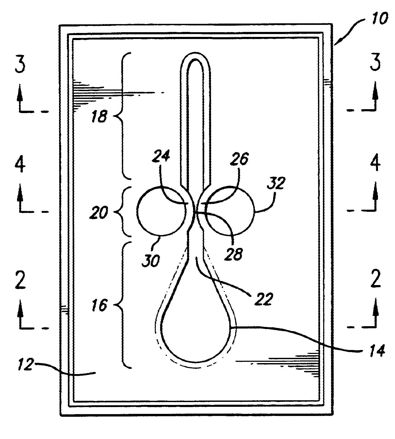
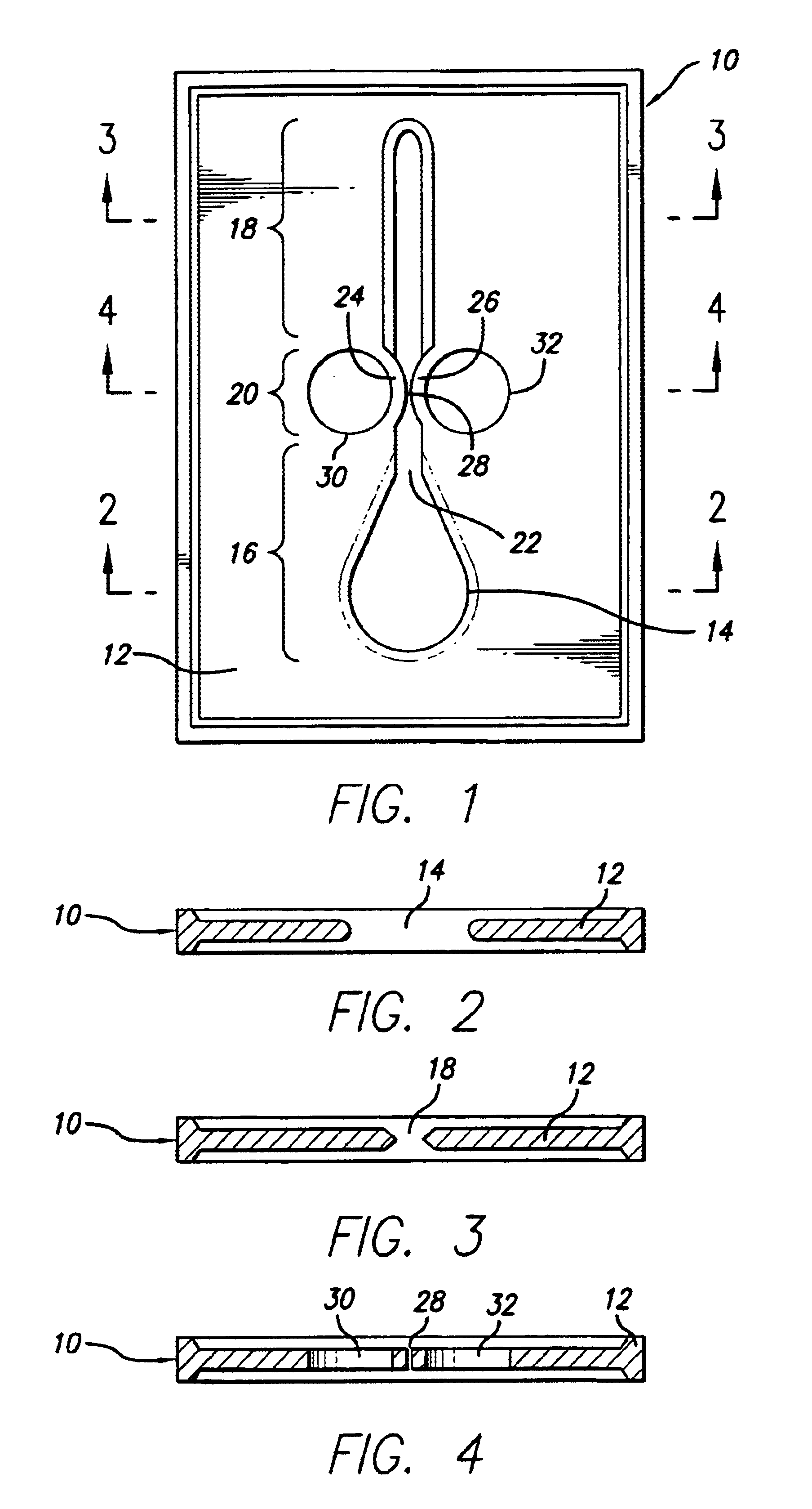
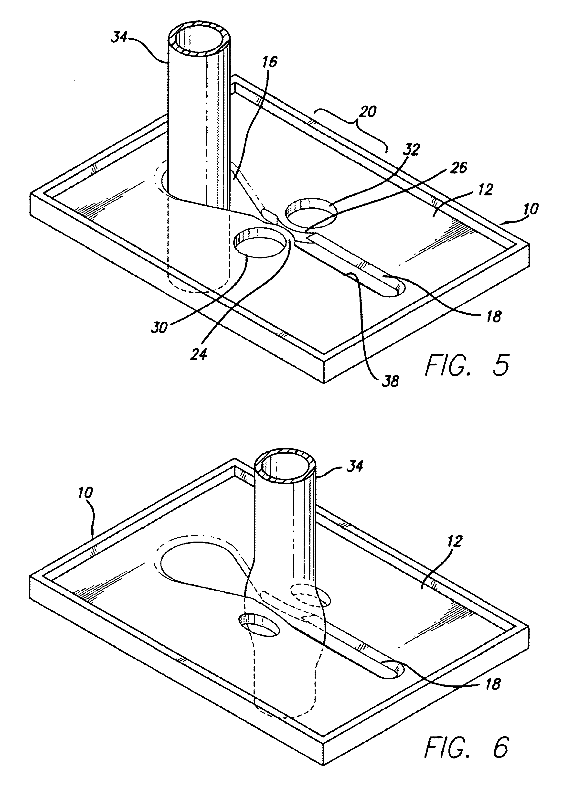
Referring now to the drawings in more detail in which like numerals used across several views indicate like or corresponding elements, there is shown in FIG. 1 a slide clamp 10 for controlling the flow of medical fluid through an intravenous (I.V.) tube (not shown) located through the clamp. The clamp includes a plate 12 that forms the body of the slide clamp and a slot 14 formed in the plate. The slot includes a flow section 16, shown in cross-sectional detail in FIG. 2, and an occlusion section 18, shown in cross-sectional detail in FIG. 3. The slot further encompasses a pinch zone 20 located between the flow section and the occlusion section for resisting the accidental dislodgement of the I.V. tube from the occlusion section to help prevent hazards associated with free flow, as discuss above.

The pinch zone 20 appears as a necked down area and provides a slot length of reduced width in comparison to the occlusion section 18 and thus functions as a stop that resists movement of a ...


PUM


Abstract

A slide clamp includes a slot formed in a plate though which a fluid tube is mounted. The tube may be moved to a flow section of the slot or to an occluding section of the slot. Interconnecting the flow and occluding sections is a pinch zone in which the slot is narrower than the occluding section. Because of this narrow slot, the pinch zone resists movement of the tube from either the occluding or the flow sections into another section. The pinch zone includes a pair of curved beams that are formed as a result of apertures formed in the plate at locations laterally outward from the slot of the pinch zone. As a tube is forced from the occluding section to the flow section the curved beams flex outwardly permitting the tube to pass. However, if enough force is not applied to the tube, it will not overcome the curved beams and they will stop movement of the tube. After the tube has passed, the curved beams resiliently return to their rest position once again providing a stop. The beams are symmetrically shaped and will permit movement of the tube in either direction. The apertures also provide identification markers for the slide clamp.

Description

BACKGROUND OF THE INVENTIONThe present invention relates generally to clamps used to control the flow of medical fluid through an intravenous (“I.V.”) tube, and more particularly, to a slide clamp that safeguards against the inadvertent movement of the clamp from an occluding position to a non-occluding position on the tube.Physicians often desire that medical fluids be delivered to a patient with precision. Therefore, instruments such as infusion pumps are used to regulate the delivery of fluids with a high degree of accuracy. Such infusion pumps provide an occlusion of the fluid line at all times. That is, there is never a direct flow path from fluid source to patient at any time, although the point of occlusion provided by the infusion pump varies. An undesirable situation may occur when fluid is free to flow through the I.V. tube without regulation by the infusion pump or other instrument. This condition is known as a free flow hazard. Activities such as priming of the fluid lin...

Claims


Application Information

Patent Timeline
Patent Type & Authority Patents(United States)
IPC IPC(8): A61M39/00A61M39/28F16K7/00F16K7/06
CPCF16K7/066A61M39/287
Inventor BOYNE-AITKEN, DAVID E.
Owner CAREFUSION 303 INC
Why Eureka
Try Eureka