Cooler for electro optic device and projector

a technology of electro optics and cooling fans, which is applied in the field of cooling fans for electro optic devices and projectors, can solve the problems of difficult effective utilization of space, large volume of projectors, and large volume of projectors, and achieve the effects of reducing the load of fans, reducing noise, and simple structur

Inactive Publication Date: 2005-01-11
SEIKO EPSON CORP
View PDF30 Cites 24 Cited by
  • Summary
  • Abstract
  • Description
  • Claims
  • Application Information

AI Technical Summary

Benefits of technology

According to such a constitution of the present invention, since the invention comprises the above-described cooler for the electro optic device

Problems solved by technology

Meanwhile, merely to provide the cooling fan in the vicinity of the liquid crystal panel of the optical unit will only lead to the bulkiness of the projector due to the cooling fan.
Further, since a projection lens is cylindrical, such a projection lens will cause a dead space around this projection lens, which is a space hard to utilize effectively.
However, since the conventional projector disclosed in the above-described Japanese Patent Laid-Open No. 11-160793 is

Method used


Image

  • Cooler for electro optic device and projector
  • Cooler for electro optic device and projector
  • Cooler for electro optic device and projector

Examples


case 23

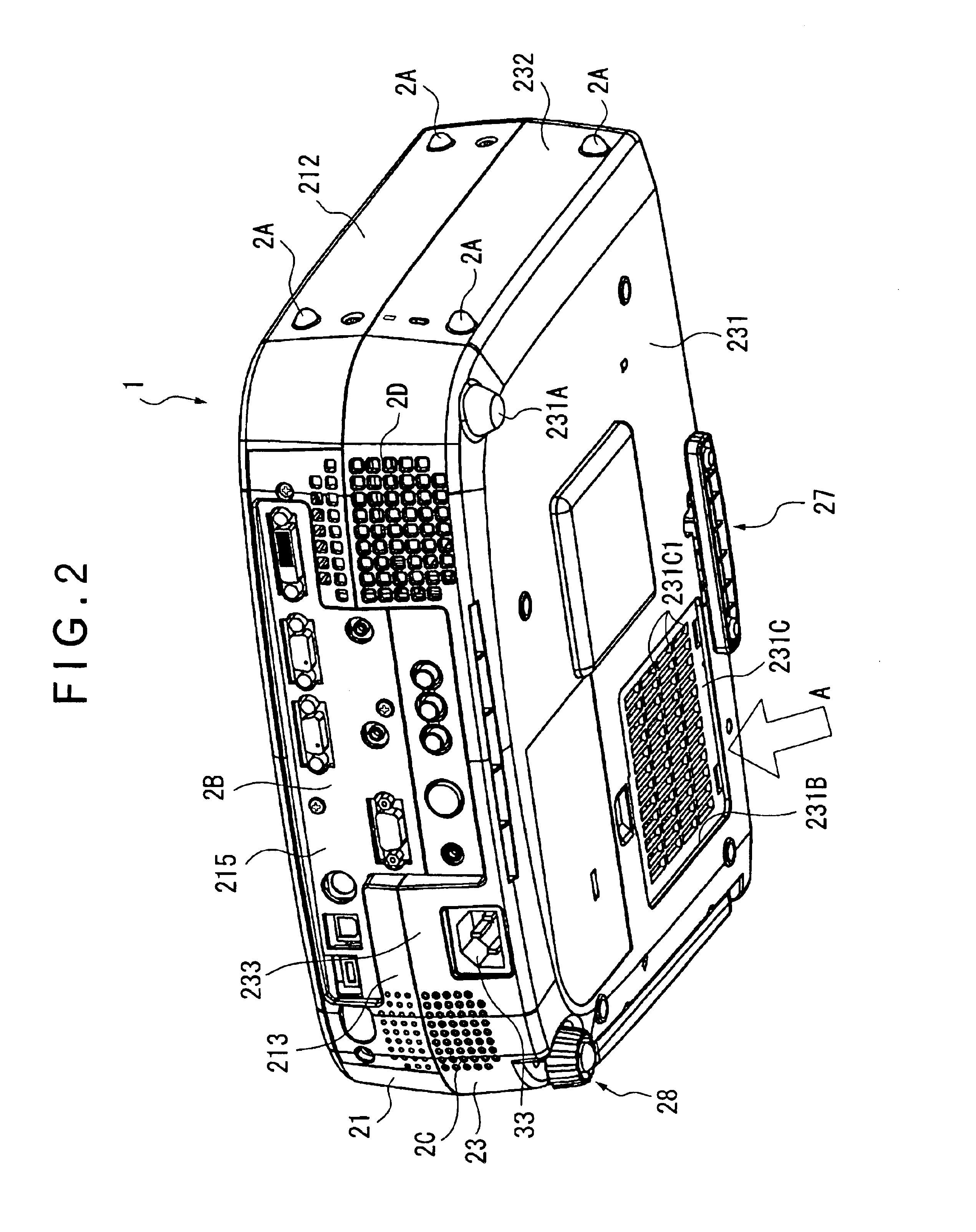
The lower case 23 is formed of a bottom face portion 231, a side face portion 232 provided on its periphery and a back surface portion 233.

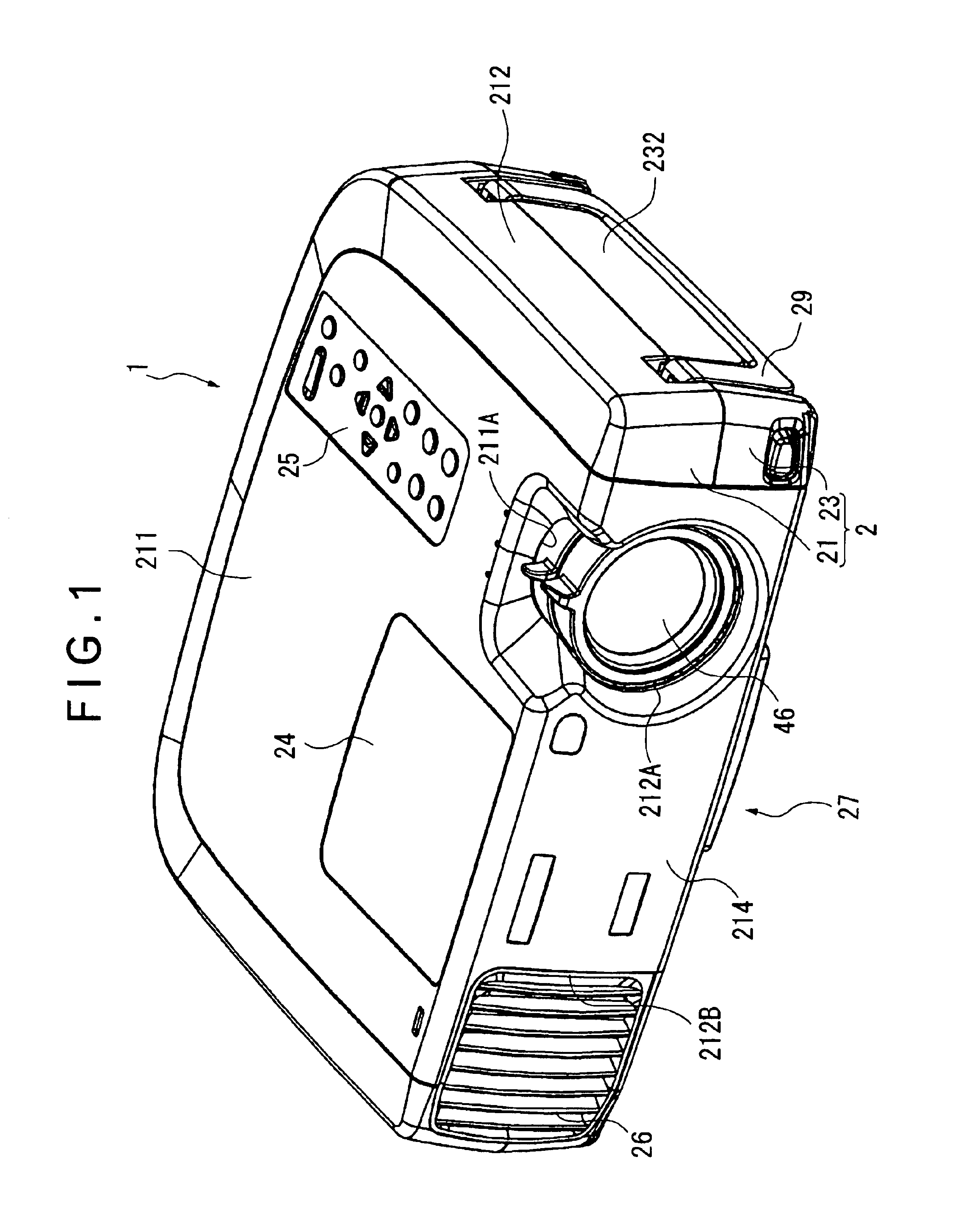
The forward side of the bottom face portion 231 is provided with a position adjusting mechanism 27, which adjusts an inclination of the whole projector 1 and positions a projection image. Further, the one corner portion of the rear side of the bottom face portion 231 is provided with another position adjusting mechanism 28 which adjusts the inclination to another direction of the projector 1, and the other corner portion is provided with a rear foot 231A. However, the rear foot 231A is unable to adjust the position. Further, the bottom face portion 231 is provided with a suction port 231B for a cooling air. Further, a cover body 231C, which opens plurality of suction port 231C1, and covers the suction port 231C1 in a lattice form, is detachably provided with the suction port 231B.

The one of the side face portions 232 is provided with mounting por...


PUM


Abstract

A panel cooling system A has a pair of Sirocco fans 51A, 51B arranged at both sides of the radial direction of a projection lens 46, a suction duct portion 52A and an exhaust duct portion 52B. The suction duct portion 52A communicates a suction port of the undersurface of an armored case 2 with a suction side of each of the Sirocco fan 51A, 51B, and the exhaust duct portion 52B communicates an exhaust side of each of the Sirocco fans 51A, 51B and color lights R, G, B of an optical part. Thereby, a cooling air is blown to the vicinity of each light incident position of the color lights R, G, B of the optical part for approximately the same air quantity, so that the cooling of the optical part is performed

Description

TECHNICAL FIELDThe present invention relates to a cooler for an electro optic device and a projector. More in particular, the invention relates to a cooler for an electro optic device which modulates a light flux emitted from a light source according to image information and projects it from a projection lens and a projector comprising the cooler for the electro optic device.BACKGROUND ARTConventionally, for example, there has been known a projector of so-called three-panel type which synthesizes light colors modulated by an electro optic device such as liquid crystal panels according to image information, and magnifies and projects a color image through a projection lens. An optical unit of this projector separates the light flux emitted from the light source into light colors of three primary colors of Red (R), Green (G) and Blue (B) by a dichroic mirror. Further, the optical unit modulates each color light by three pieces of the liquid crystal panels, which are the electro optic ...

Claims


Application Information

Patent Timeline
IPC IPC(8): G03B21/16H04N9/31H04N5/74G03B21/00G09F9/00G03B33/12H05K7/20
CPCG03B21/16H04N9/3105H04N9/3197H04N9/3144H04N9/3141
Inventor ARAI, JUNMATSUMIYA, TOSHIOFURUHATA, MUTSUYA
Owner SEIKO EPSON CORP
Why Eureka
Try Eureka